6
The CF299 (Sea Dart) Frigate1
The CF299 missile system, later Sea Dart, was completing development in the early 1960s and following the project study it was thought ‘…will be much cheaper than Sea Slug 2 and small enough to be fitted in frigates’2 not much bigger than a Leander. Sea Dart was a semi-active homing ramjet with tandem rocket boost. Two Type 909 trackers illuminated the target. Using valve technology, it was not very reliable. Two missiles could be fired every 40 seconds. It was stowed vertically in a rotating drum (height 172in).
There were a number of ship design studies, all with the same armament.
One twin CF299 with two trackers and 38 missiles
One Ikara with 20 missiles
One AS mortar Mk 10 with 60 missiles3
One SS 11 or 12 mount with 76 missiles
Anglo-Dutch radar, Asdics
Steam-powered options had either two 15,000shp units giving 27kts or two 20,000shp units for 28kts. Endurance varied between 3000 and 5000 miles at 18kts. There were also gas turbine options but these were uncertain and in 1962 Ship Department clearly preferred to stay with steam. YARD carried out a very detailed study of both first cost and through life cost of various machinery options and came down strongly for all steam at that date.
Though CF299 was smaller than Sea Slug and its vertical stowage made it easier to fit into a ship, a drum stowage for 20 missiles was still large, affecting the hull lines forward.4 Replenishment at sea (RAS) with missiles was difficult, particularly the movement from the landing position to the launcher and alignment of the missile so that it could be struck down. Later, the figure of 20 minutes per missile for RAS would be quoted. Elaborate safety tests were carried out at Shoeburyness to ensure that the accidental ignition of one rocket motor would not ignite the whole magazine. Air-loaded accumulators were arranged to spray water into the rocket mouths in the event of fire.5
It was intended that the Type 909 tracker offices should be pre-outfitted but the requirements for alignment and stiffness of support made this impossible. The estimated cost was £8.4 million (1962) when a Leander would have cost £5.25 million. Displacement ranged from 3400 to 4300 tons, but the cost did not change much with size, being governed by armament and machinery. Increasing the complement from 275 to 350 increased displacement by 200 tons.
In January 1963 there was a study of the effect of speed on the size and cost of CF299 frigates.6

Tupper tells a sad story of another study. He was asked to look at the cost of doubling the endurance. This meant adding 100 tons of structure and 400 tons of fuel, total 500 tons. Everything was done in a hurry and the cost estimators took their standard rate of £1000 per ton for 500 tons making £0.5 million. This was quite wrong as fuel is not included in the first cost of a ship and structure at that date cost much less than £1000 per ton. To make matters worse, the DG Ships then doubled the estimate to be on the safe side. Incredibly, Controller redoubled and it was decided that the extra endurance was not worth £2 million!
In April 1963, the Director of Plans suggested that an annual building rate of 2½ CF299 frigates and 2 corvettes could be afforded. About this time a ‘Post Leander is mentioned as a cheap frigate. The CF299 studies were important as they were to grow into the Type 82 (Bristol) whilst from 1963 a series of corvettes were designed to supplement the frigates, a series which was to grow into the Future Light Frigate (FLF) discussed in the next chapter.
Some CF299 Options


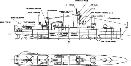
Type 82 destroyer Bristol. Originally intended as an escort for the new carriers, she had no role when CVA-01 was cancelled. This drawing and the sketch show her in original configuration with the Anglo-Dutch Type 988 ‘Broomstick’ radar and an AS mortar Mark X. The second funnel was not divided at this time. (PRO: drawing DEFE24/38; sketch ADM 205/220)
Type 82 – Bristol
Four of these ships were planned as escorts for the new carriers (CVA-01).7 They were intended to provide protection against surface ships, submarines and aircraft. They could operate as pickets or as Local Air Defence Control Ship, while the 4.5in Mark VIII gun gave them a considerable capability for shore bombardment.
The Type 82s were seen as following on from the ‘County’ class though they were designated in the frigate sequence as Type 82 until 1965, but the different configuration of the missile meant a radically different style of ship.8 As well as Sea Dart with 38 missiles (in development from 1962), they carried the Ikara anti-submarine weapon,9 an AS mortar Mark X and a 4.5in Mark VIII (three new weapon systems); as they would be operating with the carrier they did not need to carry a helicopter. Their main radar was to be the Anglo-Dutch Comprehensive Display System, Type 988, ‘Broomstick’.10
Early studies by YARD suggested a new, all-steam plant, but it was decided to develop the COSAG plant of the ‘County’ class. However, it was found necessary to design a new, larger steam plant and the gas turbines were to be Olympus, so losing any benefit of standardisation. Tupper wanted to put the Olympus over the transom with electric drive to the shafts to save the space needed for uptakes and downtakes – he even considered the use of air jets; very uneconomical but a great saving in weight and space.11 In later studies twin funnels were arranged aft to ease replacement of the Olympus through the uptakes.
The ships’ main role died with the cancellation of the carrier, but it was decided to build one ship as a trials vessel for Sea Dart, the Type 988 radar, other weapons and the machinery.12 Type 988 would have had a very large dome and stringent requirements for vibration and environment implied a stiff – hence large – bridge structure. All this obstructed the air flow over the forward (steam) funnel so Tupper devised a scheme with a big air channel under the dome.13 It was intended to pre-outfit some of the offices. In order to meet requirements for alignment this meant a heavy deck structure. Even so, the normal working of a ship in a seaway and deflection due to solar heating (several inches) meant that such movements had to be measured and corrections fed into the radar system. A particularly valuable system was the Action Data Automation Weapon System (ADAWS-2) which co-ordinated input from all sensors and navigation systems and processed it for use in weapon control.
The Bristol was designed in the same room as the ‘County’ class section to get an immediate feedback from the earlier ships.14 John Coates, constructor on the ‘Counties’, had spent 3 months at sea in an early one and written a valuable report on possible improvements. Bristol was the last ship designed ‘in-house’ and great attention was paid to the passages on 2 deck to get the run of pipes, air conditioning and wiring correct. The environment was tightly specified – temperatures, vibration, shock and noise. The movement of men and stores through the ship was studied and optimised using work study methods. Bathrooms and heads were concentrated in blocks over the sewage treatment plants. There were numerous trials at Shoeburyness on magazine safety, including the novel scheme for injecting water into a burning rocket exhaust mentioned earlier.
In 1965 the estimated cost of the first ship was £16.25 million with follow-on ships £1 million cheaper. This was the same order of cost as the ‘Counties’ at 1965 money value for a much more capable ship and requiring a smaller crew. The design complement was 380, 70 men less than the ‘County’, with accommodation for 433 allowing for a training margin and additions during the ship’s life. The cost of the destroyers could be contained within the planned budget by building a number of ‘cheap’ Type 19 frigates in parallel (see Chapter 7).
Tupper started to develop a new approach to stability standards but on a visit to the United States discovered that Sarchin & Goldberg were working on similar lines but were well ahead, so their criteria were adopted for Bristol (see Chapter 12).15 She had no structural problems in service, a rare boast – Tupper thinks this was because there was adequate time in the design stage to get it right. She was laid down at the end of 1967 and completed in March 1973. Used mainly for weapon trials, Bristol received little in the way of updates. She was very badly damaged by a fire in autumn 1973 and for a considerable time ran on gas turbines alone.16
In 1967 consideration was given to a stretched Type 82 to replace the Tiger class as helicopter ships.17

Destroyer and Frigate Studies 1966
When the carrier CVA-01 was cancelled future plans for escorts envisaged more Type 82s (above, costed at £20.75 million in the report), whilst frigate studies were in hand for the Type 19 (Chapter 7). The Future Fleet Working Party (Chapter 4) took the opportunity to review the whole escort programme – destroyers, frigates and even small patrol vessels – in nine studies.18 Though many of the studies are individually more appropriate to the next chapter it seems best to treat the whole escort scene together. There was the eternal problem of quality versus quantity linked with a desire for a common hull for AA and AS ships. These studies are important as showing what was technically and financially feasible in the mid-1960s and because the studies led directly to the Types 42, 22 and 21. Indescending order of size they are reproduced overleaf.


These two views of Bristol show some of the novel equipment which she took to sea – Sea Dart, 4.5in Mark VIII, Olympus gas turbine and the ADAWS-2 data system.
(Mike Lennon)
Comparison with the actual Types 42, 22 and 21 suggest that the choice lay near the top of the respective ranges. At the top real savings can be made for a very small loss of capability – was it really necessary to have Match, Ikara and an AS mortar? At the bottom end capability virtually disappears for very little saving in cost.
Type 42
Though the Type 42 is generally – and largely correctly – seen as a ‘cut price’ Type 82, it also had roots in the Future Fleet Working Party studies outlined in the previous section and in the earlier CF299 studies. The project director for the Type 42 (Sheffieldclass) was M K Purvis who, in 1974, told RINA that the design was constrained by price, initially about £12 million, and displacement limited to 3500 tons, which could only be met by accepting various limitations; in particular, length was to be a minimum in the hope of reducing cost.19 Design standards were to be similar to those of the later Leanders but with gas turbine machinery. There were to be no margins for future updates and there were other economies, such as a single anchor,20 combined galley for officers and men, and armament was limited to existing equipments.
The Board sub-committee on the report of the Future Fleet Working Party debated margins on cost and possible enhancements.21 The original DNC estimate was £10.5 million, to which Controller added £0.7 million (10 per cent) to first-of-class costs on the ‘ship’ side and £0.6M (16 per cent) to that for weapons, making a cost of £12 million for the first ship. There was then lengthy discussion over the possible fitting of a second TIR (Target Indication Radar – later 909). It would add some £0.5–0.75 million but would virtually double the capability in a high threat environment, though in a lesser threat, which was what the Type 42 was primarily designed for, the benefit was less. Various cost saving measures such as deleting either the gun or sonar fit were considered and rejected. DCNS pointed out that over the intended programme of thirteen ships (completing by 1980–1) the total additional cost would be about £10 million, less than the cost of a single ship, and the second TIR was accepted. This is an all too familiar problem: adding weapon capability will always seem cost effective – the phrase ‘More bangs per buck’ was often used – but with a fixed budget it may mean fewer ships and less rather than more capability in the fleet.
There was also discussion over the fitting of a close-range AS weapon, Terne, a Norwegian rocket-propelled depth charge. Though it was seen as desirable, it was decided not to fit it. The Type 42 had an unusual rounded transom which formed a high stern wave. Some instability in the flow often led to an unsymmetrical stern wave, higher on one side than on the other but there was no adverse effect on performance.
Exmouth
It was clear that Whitehall, politicians and admirals would only agree to an all gas-turbine fleet after a full scale demonstration. Vallis writes, ‘Eventually, after much politicking, lobbying and persuading … approval was gained to convert Exmouth (Blackwoodclass, Type 14) to all gas turbine propulsion.’25 She was given a single Olympus gas generator exhausting into a special power turbine. There were two Proteus for cruising. Special features were required to keep salt water out of the air supply and the engines had to be screened with blastproof containment. ‘Nevertheless, at a stroke fuel consumption was reduced, on-board maintenance was cut, availability was increased and the working conditions in the machinery space were improved beyond imagination.’ The gas turbine had arrived.

Type 42 destroyer variant of 1967 with a single tracker/illuminator radar (Type 909). The capability was almost doubled by fitting a second Type 909 at moderate cost. (Drawing by John Roberts from original – in PRO DEFE 2/239)

Type 42 destroyer. This drawing was produced in February 1968 for presentation to the Board of Admiralty. The ship at this stage carried a twin-barrel GWS 30 launcher as developed for the Type 82.
(Drawing by John Roberts from original in PRO ADM 281/291)

First-Rate AS Frigate (Study 381). This was a diesel-engined ship22 (four A016) of 4400 tons deep, also known as the Type 17, dating from 1964. There were two engine-rooms with a slight separation. The armament included Ikara, two AS mortars, Match (Wasp helicopter) and a 4.5in Mark VIII. There was a full sonar fit, including VDS. (PRO DEFE24/238)

First-Rate AA Frigate (Study 382). This had the same dimensions and the same machinery fit as the AS ship but the internal arrangements were different. It is probable that a large proportion of the drawings would have been common. It carried Sea Dart with two Type 909 trackers, two 40mm Mark IX and Match.

Medium AS Destroyer (Study 392). This design was cost limited to £10.5 million and 3500 tons. It was to carry as many of the following as possible within these limits: Ikara, 4.5in gun, Mortar Mark X, helicopter with hangar and VDS – but only the first three could be accepted within limits. There were two machinery spaces; the engines are not specified but were probably AO16 diesels.

Medium AA Destroyer (Study 391). This ship had the same dimensions and machinery as the Medium AS ship but bulkhead spacing was different. The main weapon system is described as ‘Seadaws 100’ but the drawing shows a single-arm Sea Dart launcher (26 missiles) with a single tracker. There was also a 4.5in gun and Match. The mortar, VDS and full GWS 30 (Sea Dart) were omitted on cost grounds. Though this may have been the starting point for the Type 42 it differed in almost every aspect.

Simple Specialised AS Frigate (Study 390). This was the smallest and cheapest ship which could carry Ikara (vertically-launched, without special weapons). It also had Sea Cat (vertically-launched PX430 [which became Sea Wolf] when available) and two 40mm. The machinery was Olympus/Tyne.
Simple Specialised AA Frigate (Study 389). The AA equivalent of the above with Seadaws 100 (single-armed Sea Dart launcher, 26 missiles with one tracker) and two 40mm. Once again, though the dimensions and machinery were the same, bulkhead arrangement was not. Common-hull AA and AS ships are not an easy undertaking, particularly when designed to a limit. Less obvious, but very important is that the AS ship will almost certainly need more attention to noise reduction.23
Standard Frigate (Study 387 modified). This was another variant of the Type 19 (qv) but with only one Olympus per shaft (30–32kts) and two Venturas per shaft for cruising. Armament was a 4.5in gun, Sea Cat (PX430A – Sea Wolf – in later ships), two twin 20mm Oerlikon, Match with Wasp (ability to land a Wessex in good weather), two torpedo tubes, two Penguin (a Norwegian SSM).

AS Patrol Vessel. (Study 920). Roles as above but also AS escort. Armament: mortar Mark X and one 40mm; Wasp helicopter with limited maintenance. The machinery fit was one Olympus and two Tynes driving two shafts though a single gear box.24
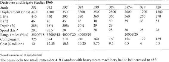

Patrol Vessel (Study 919). The roles were peacekeeping, fishery protection and engaging lightly armed craft. It would work from a base or depot ship – ‘accommodation would be cramped’. Armament would be a 4.5in gun and PX430. No sonar and only minimum radar would be carried.
(All Future Fleet Working Parts drawings PRO DEFE 24/238)
The Vosper Mk 5 was also included in the report.
By this time there was considerable knowledge of the advantages and disadvantages of the gas turbine in warships. The airflow was about three times as much as in a steam plant. Some 75 per cent of the heat of combustion went into the exhaust gas at 500°C and 200ft/sec – in a steam plant 20 per cent went up the funnel and 60 per cent into the sea. The gas turbine air flow had to be unobstructed as lin water gauge back pressure would reduce the power from an Olympus by 100shp. The ducts also had to be free of obstructions which might excite damaging eddies in the flow. The exhaust ducts for Olympus were about 6m2, which meant that they could be used to change engines. The ducts had to be lagged as the inlet could be very cool and the exhaust would certainly be hot. About 40m3 was needed for salt spray eliminators.26
The best steam plants needed about the same space and would be 15 per cent heavier. The gas turbine plant would be about 10 per cent more on initial cost but save in life cost. A very important advantage of the gas turbine was that it could start from cold in two minutes.
Olympus/Tyne: Types 42, 21, 22
The Type 42 (Sheffield) was to be small, cheap and with a small crew. All gas-turbine propulsion seemed to meet the requirement very well; full power would come from two Olympus, each driving one shaft with a CP propeller. The intended cruising speed was higher than in previous ships and the Tyne fitted the bill. Advice from the principal operator of the Tyne, British European Airways, was that it was the worst engine they had ever used! However, the Navy’s luck was in for once, as the effort to remedy these problems in aircraft had succeeded, and the marine Tyne was to prove very reliable. A new free power turbine was needed and many materials had to be changed to suit the marine environment.
The main propulsion system of these classes proved very reliable and led to a revolution in working conditions. The auxiliary machinery posed more problems. The ‘Tribals’ had Allen 500 KVA gas turbine alternators, which were efficient but complicated. Output fell off quickly due to fouling of the compressors and heat exchangers and cleaning was a lengthy task. The ‘County’ class had Ruston TA alternators which were simple, rugged and reliable but bulky and inefficient. The machinery was arranged in four spaces – generator, Olympus, Tyne, gearing and generator – used in several other classes.27

Exmouth, the first RN all gas turbine frigate. The baffles in the big air intakes fore and aft of the funnel were intended to keep salt water out of the turbines.
(MoD)
It was decided to fit diesel generators in the new classes. Experience of diesels in the older frigates had been confined to harbour and emergency use and the change to continuous operation brought many problems. The supply of fresh water was also difficult and in the Types 42 and 21 auxiliary boilers and steam-heated distillers were fitted. This equipment turned out to have a heavy maintenance load.
The biggest changes with the all gas-turbine plant came in the control of the machinery, with much faster response, and in the handling of fuel. Electronic controls, including bridge control, led to a revolution in watchkeeping practice and hence in training. Fuel was stowed in a water-displacement system which meant providing a very elaborate fuel cleaning system and the separation of the least trace of water. Total commitment to ‘repair by replacement’ was inevitable and demanded a major effort in spares cataloguing and supply.28 Cruising speed was set by the Tynes, which, at full power, used 0.5 pound per shp hr (1.0 including auxiliaries).
The old, heavy steam machinery made good ‘ballast’, keeping the ship’s centre of gravity low.29 The downtakes and uptakes for a gas turbine are very large – 6m2 for an Olympus – though there was an advantage in that gas turbines could be changed afloat via the air trunks. A hydraulic ring main was fitted, working the capstans, boat davits, winches, RAS mast and storing lift. Since these equipments were not in use simultaneously the power needed for the pump was only 17.5hp.
Controllable-pitch propellers were fitted to give astern power, which led to difficult problems in propeller design, particularly the air supply down the shafts and into the (moveable) blading for the Agouti installation. The big shafts and supporting brackets, together with constraints on blade design, led to an overall loss of 6 per cent in propulsive efficiency. The engine-room staff was about 20 men less than in a steam installation.30 Sheffield completed with a strange funnel intended to reduce infra-red signature.31Two pairs of stabiliser fins of the same design as used in the Leanders were fitted. A double bottom was incorporated containing fuel tanks, some of which could be water compensated in the light condition. For the first time, rotary vane steering gear was fitted with a considerable saving in space and weight.32 Twin rudders gave a turning circle whose diameter was 3½-4 times the ship length.

A fine view of Southampton, a Batch II Type 42.
(MoD)

Sheffield with the original funnel intended to reduce infra-red signature from the exhaust plume. Note the absence of an anchor on the port side.
(D K Brown collection)

Manchester, a lengthened Batch III seen in rough seas off Australia. It is not easy to judge from photographs but it is likely that the weather here is Sea State 5–6, representing 4m significant wave height.
(MoD)
The armament was a twin Sea Dart launcher with two Type 909 directors and 22 missiles.33 There was a single 4.5in Mark VIII and during and after the Falklands War various close-range guns were fitted, most ending with two Phalanx CIWS. A Lynx ASW helicopter was fitted, with hangar. Accommodation for 300 was generally to the standards of the later Leanders. Ship’s officers had single cabins with multi-berth cabins for trainees and CPOs. The ships were fully air-conditioned for tropical service.34
The class put on weight during building, which might have caused the Argentine Hercules failing to reach contract speed. A weight-saving exercise was agreed with Vickers but, unfortunately, too many longitudinals were omitted from 01 deck and the first batch had to be given external stiffening. The second batch were easily corrected in build.
Great attention was paid to corrosion protection, with all ‘wet’ spaces protected by sprayed metallic zinc, which has paid a considerable dividend in reduced refit work.35 Coventry was the trials ship for improved application of paints. Preparation and painting were done with great care and it was hoped to show that this could be justified by increased corrosion-free life. Alas, the trial was ended by Argentine bombs. Exeter had an early application of self-polishing anti-fouling paint – her blue bottom (the only colour then available) caused some amusement but this trial was a great success, leading to considerable fuel saving.
In 1978 it was approved to build the last four ships to a modified design.36 They were lengthened by 50ft and given 3ft more beam. The extra length was all forward so that machinery and transmission drawings needed little alteration. These much bigger ships were about 1.5kts faster with the same machinery. Their structure was designed using a new, dynamic approach which was very difficult to use and a mistake was made, so that this batch, too, needed stiffening.
Some Comparisons
It was estimated that a steam Type 42 would be 250 tons heavier – 100 tons of machinery, 60 tons more fuel, 50 tons in accommodation and 40 tons of structure. The steam machinery would be 10 per cent cheaper but extra structure and accommodation would take back 7 per cent. However, upkeep of the gas turbine plant would be 5 per cent less through life. Engine-room complement would be reduced in the gas turbine ship by 17 plus 3 support staff leading to a 37 per cent reduction in through-life cost.
A diesel plant would be 250 tons heavier with machinery spaces 20ft longer. In the oil crisis of the early 1970s coal burning was considered, with the conclusion that, overall, the economic solution was to convert coal to oil ashore and continue to burn oil.37
The Type 43 and Type 44
The Type 43 was intended to follow on from the Type 42 but armed with the Sea Dart Mark II.38 The primary role was to protect a task force39 from air-launched missile attack. This set the requirement for the number of ‘channels of fire’ – one Type 909 director and a single missile. There were two basic variants. The smaller one resembled a Type 42 with one twin launcher forward and directors fore and aft, while the larger had a twin launcher at each end and four directors. Allowing for refits, the number of big ships needed would have been rather over half the number of small ships.
With launchers at both ends, the helicopter deck had to go amidships in a long gap between the two superstructure blocks. This was not popular with airmen but an acceptable arrangement was found. This forced the engine-rooms (each with two SM1A) apart, with two main compartments between, which was ideal from a vulnerability point of view though some thought the long shaft from the forward space was a hazard. However, intensive study of shaft damage after whipping in the Second World War and in post-war trials showed that the risk of such damage was very slight.
The long gap amidships made the early studies look horrid. Eventually, the pre-war Southampton class cruisers provided inspiration and though the Type 43 could not quite match the beauty of their predecessors, they were pretty good – even if I say so myself. The first draft Staff Target was 30kts essential, 34kts desirable and it was soon found that four SM1A would give about 31.5kts in either variant.40 There were a number of weird variants including one with two Harriers, which served only to confirm that it was grossly uneconomic to carry less than six in one ship (see Chapter 7). There was even a very quick study of a nuclear-propelled ship with two SSN plants.

Small Type 43, an updated Type 42 with Sea Dart Mark II. Simulations showed that it had little capability.
(D K Brown collection)
Increasingly, the bigger ship began to look attractive. The building cost of the whole class was less and, even more important, total crew numbers were less at a time when recruiting was difficult. Control of four ‘channels of fire’ from one ship was easier than from two. ASWE carried out computer simulations of various forms of mass attack which showed the small ship failing in every scenario and the big ship being reasonably acceptable.41 The big ship was approved by the relevant committees but Whitehall lost its nerve over the high unit cost (about £200 million), and out of committee and without studies the Type 44 was conceived.

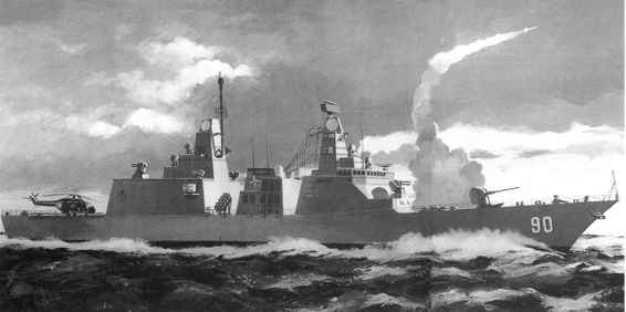
Type 43: artist’s impression (left) and profile (below) of the big variant, which seemed much more cost effective than a larger number of smaller ships. The big gap amidships was sufficient to operate a Merlin helicopter, and the aesthetic treatment owed much to pre-war Southampton class cruisers.
(MoD)

This was roughly the small Type 43, already shown to have little capability, with slightly enhanced AS capability. It was put straight into Feasibility design, but before long both it and Sea Dart Mark II were killed by the Nott Defence Review of 1980, one its few correct decision.42 It was hoped to use the Type 22 hull form though this seems unlikely given the size of the Sea Dart magazine.
The NATO Frigate
The UK joined with USA, France, Italy, Holland, Spain, Canada and Germany to design and build a common frigate. It got off to a bad start as there were considerable differences in national requirements. It was generally agreed that the emphasis was in protecting ships in company from air flight missiles. Existing point defence missile systems were ruled out as they could only cope with missiles aimed directly at them, while the new system had to deal with the much more difficult crossing target. The main threat was seen as coming from missiles launched from submarines at fairly short range, which meant the missile defence system had to have an extremely short response time.
After lengthy negotiations it was agreed to go ahead with a development of the Franco-Italian Aster missile, though it was still uncertain which warning radar would be fitted. Debate on the ship itself centred on USN rules over trunked access to vital compartments, which implied a much larger and costly ship (see Comparisons, Appendix 5). The USN, with RN support, were pressing for the compound gas turbine under development in the UK for the USN. The UK was aiming for a cheaper ship than its partners.
An impression of the proposed NATO frigate. (D K Brown collection)

A version of the Type 43 to carry two Harriers. It proved to be not worth the effort. Many studies are carried out to investigate the impact of even unlikely requirements.
(D K Brown collection)
NATO collaborative projects are usually approved and funded for one phase at a time, with a contract for that phase only placed with an international consortium. At the end of the phase work stops while all governments have to agree on the chosen option for development in the next phase. There will then be a tender exercise for the next phase so that there is a break of some 18 months between each phase. It is far from certain that the same consortium will win the new contract and, even if they do, only a nucleus staff will have been retained and the next phase will be a new start. The solution seems simple: approve a single consortium for the whole design (subject to satisfactory performance) and fund for each phase plus a continuing team while the earlier stage is being approved.
The NATO frigate as such died at the end of phase two. The head of concept, Peter Chamberlain, then produced his own ideas which was agreed informally by France, UK and Netherlands as the FUN frigate. When Italy showed interest it became the FUNI frigate whilst Greece made it the FUNGI frigate. These informal studies and discussions showed that there was still interest in collaboration.
Project Horizon
Eventually, the UK joined with France and Italy to develop a new ship around the Aster missile, though quite early on the UK decided to fit its own main radar. This design, too, failed. The UK’s partners were only proposing to build very few ships and the advantages of collaboration were diminishing. The last straw came over management structure which the UK did not believe was strong enough to control costs. (A note on the succeeding Type 45 is in Chapter 14.)
1 Though early studies were classed as frigates, the outcome was the Type 82 Destroyer and hence the whole family is dealt with in this chapter under destroyers.
2 ADM 205/183 (PRO).
3 To reduce complement Tupper suggested that the long-range Ikara and the relatively short-range mortar should be operated by the same men, since they would not be used at the same time. The naval authorities found this too difficult.
4 Some studies had up to 38 missiles. The ‘20’ missile fit was often rendered as 22 which probably included two training rounds – see N Friedman, World Naval Weapon Systems 1991/92 (Annapolis, 1991), p397.
5 This was developed by Harry Melrose of Hawker Siddeley. When the task was complete he found himself without a job and became a highly respected constructor.
6 ADM 1/28894 of 31 January 1963 (PRO); signed E C Tupper, who has contributed much to this chapter (private letter of 30 August 2001).
7 By 1965 the long-term plan envisaged eight Type 82s. DEFE 10/511(PRO).
8 The ‘County’ class carried Sea Slug with wrap-around boost, stowed horizontally. The new missile, Sea Dart (ex-CF299) was stowed vertically in a rotating drum holding 38 missiles in Bristol.
9 A guided rocket which carried a homing torpedo to the vicinity of a suspected submarine. It had been in development with Australia since 1964.
10 The name ‘Broomstick’ was selected by the Dutch, referring to the masthead brush carried by Tromp in the Anglo-Dutch Wars as a boast that he had swept the seas clear of the English fleet – whoever agreed to it in the UK did not know his history.
11 It was often proposed that a constructor should join the concept group during studies and then take the design with him into detailed design. Bristol was one of the few cases when this happened, with Eric Tupper (who has made a major contribution to this section) and was a success. Even extending this policy to overseeing was considered. He was involved in various novel schemes at this time, including a catamaran frigate and a catamaran to launch space rockets.
12 In fact, the Netherlands cancelled ‘Broomstick’ and Bristol received Type 965.
13 A naval staff officer said it reminded him of a guardsman – busby on top, nothing between the ears!
14 The desks of the two constructors were alongside each other.
15 T Sarchin and L L Goldberg, ‘Stability and Buoyancy Criteria for US Naval Surface Ships’, Trans SNAME (1962). Based largely on studies following the loss of three USN destroyers in the Pacific typhoon of 1944.
16 The fire was in the steam turbine room and burnt for several hours. Luckily, she was alongside at Newport and the local fire brigade finally extinguished it with the then novel high-density foam. The author visited the ship a few days after the fire and was told that if she had been at sea, she would have been abandoned.
17 DEFE 16/617 (PRO).
18 Future Fleet Working Party Report Vol 3. DEFE 24/238, 90724 (Originally Secret, now declassified [PRO]).
19 M K Purvis, ‘Post War RN Frigate and Guided Missile Destroyer Design 1944–1969’, Trans RINA (1974).
20 There was a second anchor stowed at the bridge front. If the chain broke, the spare anchor could be attached to the remaining chain. Additionally, it was argued that the gas turbines could be started within a few minutes.
21 DEFE 24/239 (1967) (PRO).
22 It is noted that the machinery might be altered if the design was developed, probably reflecting development of the Olympus-Tyne fit.
23 These two ‘specialised’ frigates are described in slightly more detail in DEFE 24/234 (PRO). The aim was to reduce cost and complement by reducing the weapon fit. A 20kt version with a single diesel and shaft would need 10 less men, be 20ft shorter and save about £0.75 million.
24 This was proposed for a number of studies and should have worked.
25 Rear Admiral R A Vallis CB, ‘The Evolution of Warship Machinery 1945–1990’, Presidential Address, Trans I Mar E (1991).
26 S J Palmer CB, RCNC, ‘The impact of the gas turbine on the design of major surface warships’, Trans RINA (1974), p1.
27 A A Lockyer, ‘Engineering aspects of the Type 42’, Navy (Sept 1970).
28 The consequent diminution of afloat staff and increase ashore led politicians and journalists to complain that the tail was being increased at the expense of the teeth. They could hardly have been more wrong.
29 The metacentric height in the intact condition could be restored by a small increase in beam but, with extensive flooding, a low centre of gravity is desirable. In most conditions a Type 42 should float with four main compartments flooded – post-sinking studies of Coventry with five compartments flooded showed this aim had been achieved.
30 One of the lessons of the Falklands war was that damage control was easier in a steam ship as they had more technical ratings – you can’t win!
31 Known as the Loxton bend – the Argentine Hercules had a similar funnel.
32 Rather like a paddle wheel with vertical axes; this gear had been developed for CVA-01.
33 A single launcher was originally planned.
34 J C Lawrence, ‘The Warship of the “seventies”’, Navy (Sept 1970).
35 Perhaps a little overdone, and slightly reduced in later classes with the benefit of experience.
36 Purvis says that the modification brought them back to his original ideas!
37 There was a delightful cartoon of a coal-burning Type 42 with 4 tall, thin funnels and a ram bow!
38 The author took over the concept design in mid-1978.
39 Typically, a CVS and two AOR.
40 A new Staff commander altered the target to ‘36kts desirable’ and asked me if it mattered. He was angry at my reply: ‘No, you’re getting 31.5’. To convince him we did some very quick estimates – four Olympus would give about 34kts at the expense of poor fuel consumption and no more was possible with existing machinery. New machinery, probably steam, would be needed for 36kts.
41 It was later realised that the simulations were flawed as both ships fired several times more missiles than they carried. The true conclusion was that Sea Dart Mark II was inadequate, though the big ship was still better.
42 In the author’s view it would have been cheaper to buy Aegis – even though its unit cost was high – than develop a new system for relatively few ships. The big Type could have been adapted quite easily – we looked.