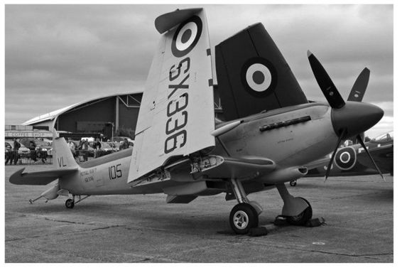
That the Royal Navy, in urgent need of fighter aircraft with modern performance for fleet and convoy protection, should in the early years of the war have turned to the Hurricane and Spitfire for a solution of their problem was hardly surprising. From the point of view of combat effectiveness no better choice could have been made than the two most outstanding and heavily-armed fighters of the day. Both of these aircraft were adapted for carrier-operation by the fitting of a deck-arrester hook and spools for catapult launching, and in this form they performed invaluable service against long-range enemy aircraft during the earlier, critical phases of the Battle of the Atlantic.

A Seafire wing in it’s vertical frame showing the wing ‘breaks’ for carrier operation.
In the later war years the Spitfire, or the Seafire, to give it its Fleet Air Arm name, appeared as a complete naval conversion with folding wings - a surprising metamorphosis indeed for an aircraft originally designed as an out-and-out land-based fighter. Such a development was desirable in a carrier-based aircraft, and became a matter of urgency with the introduction of the small escort carriers which were brought into commission to supplement the large fleet carriers.
The introduction of a hinged joint into an established design of fighter wing was a modification which would hardly be viewed with great enthusiasm at any time. In most fighter wings it was necessary to accommodate so much equipment that the normal structure was very much broken up. The basic Spitfire wing was no exception to this rule, as it housed the outward-retracting undercarriage-leg as well as the machine-gun and cannon armament, with its associated ammunition-boxes and magazines. The Spitfire main spar was also regarded as something of an obstacle to the successful accomplishment of so drastic a surgical operation. Nevertheless, the decision was made to introduce the folding wing, and the necessary modifications in design were completed in a period of some three weeks.
Two hinged joints were introduced into the original fixed wing, with the result that the span of 36ft. 10 inch span was considerably reduced. The main joint was made near the edge of the wheel well, while the outboard joint corresponded to the attachment line of the wing-tip in the original wing.
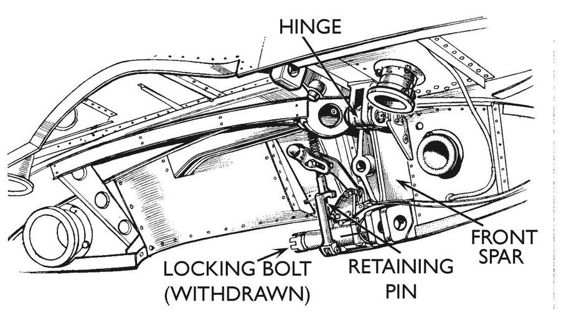
As the tip was always built as a separate unit, there was a natural division in the structure and the introduction of a hinged joint at this point was not such a basic modification - principally a matter of substituting hinge fittings, with a suitable locking device, for the original attachment brackets. At the main joint, however, the hinge entailed the division of the forward main and rear subsidiary spars as well as the modification of the rib structure.

A detail sketch of the wingtip joint and locking mechanism on the front spar. The position of the jury strut for securing the wing in the folded position is shown by the dotted line.
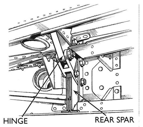
Of these alterations the most fundamental was the division of the main spar, though the section of the rear spar between the fuselage attachment and the main hinge joint was considerably strengthened.
The Seafire mainplane structure was not notably adaptable to sub-assembly breakdown, though the introduction of the folding wing imposed a measure of compulsory division into components. In general, the basic structure was the same as the Spitfire. Smaller sub-assemblies included the cannon-bay structure, the top-surface structure over the wheel-well and what was known as No. 3 sub-assembly, which included interspar ribs 14 to 16 with the associated section of the rear spar.
The strengthened portion of the rear spar, inboard of the main joint, was of I-section built up from a web- plate and two pairs of L-section pressings riveted together, with local reinforcing plates at the root. This section and the outboard portions that remained, as in the Spitfire, a built-up channel, were assembled almost entirely by female workers.
The No.1 assembly, the portion of the Seafire wing inboard of the main joint in the assembly fixture.

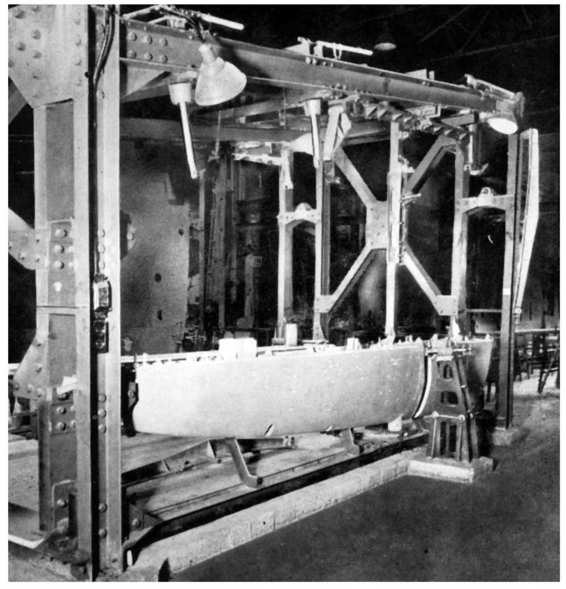
One of the wing main assembly fixtures showing the leading edge sections in position.

The interspar and trailing edge structure ready for the application of skin plating.
The main assembly fixture for the Seafire wing was practically identical with that used for the Spitfire, with the addition of locations for the main hinge-joint fittings on front and rear spars. As a structure the fixture may be described as an enlarged version of that use for the No. 1 assembly. It was an open frame of structural-steel channels with the top member sloped to conform to the sweep forward of the rear spar. The end columns of the fixture carried locations for the fuselage joint pick-ups at one end and for the wing-tip fittings on the front and rear spars at the other.
Locations for the fittings of the main hinge joint were mounted on a pedestal set into the floor for the front spar, and for the rear spar on the post mounted between this pedestal and the top beam of the fixture. This beam also carried locations for the aileron hinge brackets on ribs 14 and 19 and a boundary location for the outboard flap rib.
A dummy flap, consisting of a steel tube (representing the flap spar) with a series of projecting steel bars which served as height locations for the recessed trailing-edge strip, was mounted between the outboard flap-rib location and the end column of the fixture, for the purpose of positioning the trailing edge structure aft of the rear spar.
Details of the main hinge of the front spar showing the shear fittings and the mechanism for locking the joint.
The Seafire F Mk III was the first true carrier adaptation of the Spitfire design. It was developed from the Seafire Mk IIC, but incorporated manually folding wings, allowing more of these aircraft to be spotted on deck or in the hangars below. This version used the more powerful Merlin 55 (F Mk III and FR Mk III) or Merlin 55M (L Mk III), driving the same four-bladed propeller unit used by the IIC series; the Merlin 55M was another version of the Merlin modified to give maximum performance at low altitude. Other modifications that were made on the Spitfire made their way to the Seafire including a slim Aero-Vee air filter and six-stack ejector type exhausts. In addition the shorter barreled, lightweight Hispano Mk V cannon were introduced during production as were overload fuel tank fittings in the wings. This Mark was built in larger numbers than any other Seafire variant; of the 1,220 manufactured, Westland built 870 and Cunliffe Owen 350. In 1947 12 Mk IIIs were stripped of their naval equipment by Supermarine and delivered to the Irish Air Corps.
After the Mk III series the next Seafire variant to appear was the F Mk XV, which was powered by a Griffon VI driving a Rotol propeller. Designed in response to Specification N.4/43, this appeared to be a navalised Spitfire F Mk XII; in reality the Mk XV was an amalgamation of a strengthened Seafire III airframe and wings with the wing fuel tanks, retractable tailwheel, larger elevators and broad-chord ‘pointed’ rudder of the Spitfire VIII.

Drilling the flanges of ribs 8 and 10 for the Oddie fasteners which secured the Seafire’s cannon-access door.
Removing the heads of the leading edge skin attachment rivets to give a flush surface.

The main joint on the reat spar consisted of a simple hinge fitting. This drawing shows the strengthened construction of the inboard spar rear section.
Marking out the cut line on the leading edge skin panels. whilst on the assembly fixture. The leading edges were later removed, cut and trimmed down to size to these marked lines and finally de-burred.

The cut line for the skin panels on the upper surface of the wing was marked out from a large template mounted in the fixture. After the panels were marked out and cut, they were taken off for burr removal and dimpling.


A complete starboard Seafire mainplane ready for removal from the main fixture.
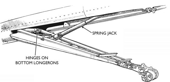
The deck arrestor hook lowered. A spring jack exterted a downward pressure whilst permitting the hook to adjust itself vertically as required.

After all the fixture stages were completed the entire wing was placed on a wheeled stand for the final assembly operations.
Sea fires were also made under sub-contract by Folland Aircraft Ltd of Southamption. This view below shows the Seafire mainplane assembly area with the fixture stages on the right and left, with a double line of final assembly trollies in between.

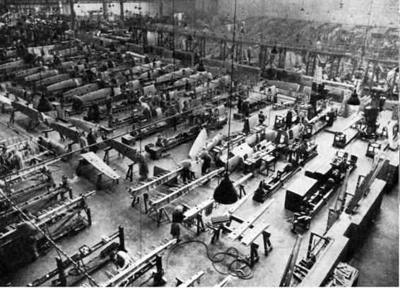
A view of one of the Folland shops showing leading-edge assembly in progress. In the immediate foreground nose ribs were being assembled to the spars. Farther back the fitting of leading edge skin plating is in progress. In the background were the fixtures for mainplane assembly.
Folland Aircraft, Ltd. had been engaged principally upon subcontract manufacture of aircraft components. As one of the Seafire group the firm was responsible for the production of stern portions (stern fuselage and empennage), mainplanes and the front-spar fuselage frame, known universally to those familiar with the Spitfire or Seafire structure as Frame 5. In the manufacture of all these components, a carefully organised system of balanced assembly stages had been worked out to make the most efficient use of fixtures and labour force available.
Seafire F XVII SX336 showing the wings fully folded and the arrestor hook.