

The front end of a Sabre showing the four compound reduction gears through which the two crankshaft pinions drove the airscrew shaft.
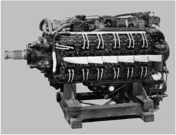
The Napier Sabre was a H format-24-cylinder, liquid cooled, sleeve valve, piston aero engine, designed by Major Frank Halford and built by Napier & Son. The engine evolved to become one of the most powerful inline piston aircraft engines in the world, developing from 2,200 horsepower in its earlier versions to 5,500 hp in late-model prototypes
The first operational aircraft to use the Sabre were the Hawker Typhoon and Hawker Tempest; however, the first actual aircraft powered by the Sabre was the Napier-Heston Racer, which was designed to capture the world speed record. Other aircraft using the Sabre were the Martin-Baker MB 3 prototype and one of the Hawker Fury prototypes.Later it became used in the early production of the Blackburn Firebrand.
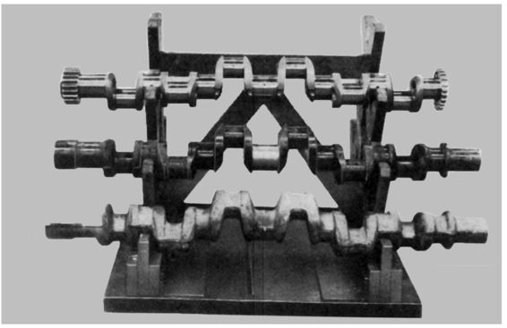
The three main phases of Sabre crankshaft production. Bottom, the rough stamping; middle: intermediate stage following heat treatment; top a finished upper shaft.
Napier first decided to develop a 24 cylinder, liquid cooled engine capable of producing at least 2,000 hp in late 1935. Although the company continued with the opposed ‘H’ layout of their earlier Dagger, the new design positioned the cylinder blocks horizontally and was to use sleeve valves. All the accessories were grouped accessibly above and below the cylinder blocks, rather than being at the front and rear of the engine as in most contemporary designs.
The first Sabre engines were ready for testing in January 1938, although they were limited to 1,350 hp.By March they were already passing tests at 2,050 hp and by June 1940 when the Sabre passed the Air Ministry 100-hour type-test, the first production-ready versions were delivering 2,200 hp from their 37 litres.By the end of the year, they were producing 2,400 hp. To put this in perspective, the contemporary 1940 Rolls-Royce Merlin II was generating just over 1,000 hp
Problems started to arise as soon as production started in volume. Until then the prototype engines had been hand-assembled by Napier craftsmen and it proved to be difficult to adapt it to assembly line production techniques. In particular, the sleeves often failed, leading to seized cylinders. After testing a whole range of materials and manufacturing methods techniques a process of nitriding and lapping the sleeves helped resolve the problem.
By 1944, the Sabre V was delivering 2,400 hp consistently, and the reputation of the engine started to improve. This was the last version to see service, powering the Hawker Typhoon and its derivative, the Tempest.
Two halves of a finished Sabre crankcase On the left is seen the cylinder block face and on the right the joint face is uppermost.


An overall view of Napier’s crankcase machining department. Each line of machines is flanked by a roller conveyor.
The assembly shop at Napiers was divided into six main departments comprising sub-assembly first-build, engine first-build, engine strip and sub-assembly rebuild aftertest, engine rebuild for final test, and packing and despatch: the sixth department was reserved for special work and building for retests.
The sub-assembly first-build department was sub-divided into a number of self-contained sections for building and rig testing the various units. In all, there were seven main units comprising the crankcase complete with crankshafts and con-rods; cylinder blocks complete with worm shafts, sleeves, worm wheel cranks, supercharger drive and gear shafts; nosepiece assembly comprising the airscrew shaft, layshafts and carrier plate; auxiliary drive case; bottom cover and sump, including coolant pumps and petrol pump drive; supercharger; various small components such as pistons, junk heads, oil filter, and hand turning gear.

Balancing the sleeves and timing the port opening.

Part of the cylinder block assembly line, with each block mounted on rotatable fixtures.
Once the engine had been on static test it was returned to the assembly shop for complete strip and examination, during which each component was checked and its history details logged. Rebuilding took place in the same sequence as that followed on the first-build line, and the re-assembled engine returned to the test house for final test. A short motoring period was carried out to satisfy certain assembly standards, ignition-plugs were fitted and ‘running in’ again commenced. During the final test-running period was reduced to one hour, at the completion of which tuning, auxiliary pressures and temperatures were again carefully checked. When all adjustments were satisfactorily completed the previous test conditions were again carried out, finishing with the acceleration test. The engine was then removed and the sump filters re-checked prior to removal for packing and despatch.
The last stage of assembly when all pipes and ignition control harnesses were fitted. This was followed by air, water and oil tests of the various engine passages.
