
The destroyers of all types were fitted with six Wagner boilers (except Z 9–16. which had Benson boilers). Two sets of turbines provided the drive. Types 1934, 1934A and 1936 had an electrical plant with two turbo- and three diesel generators, and had two shafts and one rudder. Type 1936B (Mob) had one turbo-generator, and 1936A and 1936A (Mob) two; and these three types were equipped with four diesel generators and had two shafts and two rudders.
Boilers
The Wagner was a high-pressure, hot-steam boiler with natural water circulation, equipped with exhaust gas and feedwater preheaters (two steam-heated and one fresh-steam stage), and had an effective operating level of 83 percent. The working pressure was 70atm, with steam temperature at 480°C (later reduced to 450°C).* Between 35 and 46 tonnes of steam was raised per hour. The boiler was constructed as both a single- and double ender and had two Saacke burners.
The Benson was a forced-How boiler, the feedwater being forced through the boiler tubes, evaporated and then superheated. The operating level was 77 per cent. the working pressure 110atm and the working temperature 510°C. The Benson boiler did not perform well and was liable to break down, and it was not until another drum as a steam collector was added in the late 1930s that it was finally made manageable. As these boilers were a Blohm & Voss/Benson development, they were dubbed ‘Blohmson’ during the continuing debate about the La Mont boiler.
The six boilers installed in the Type 1936A destroyer were of two different sizes, four producing 54 tonnes of steam per hour and two producing 48 tonnes. There were three boiler rooms; later projects had two. The exhaust pipes of boiler rooms 2 and 3 were trunked through the forefunnel, the after funnel serving boiler room 1.
BOILERS
|
Z 30 |
Z 1–8 |
|
|
Type/manufacturer |
Wagner |
Wagner-Deschimag |
|
Construition |
Double-ender with two Saacke burners |
|
|
Heating surface, per boiler: |
||
|
Vaporiser |
392m2 |
400m2 |
|
Superheater |
100m2 |
100-120m2 |
|
Air preheater |
564m2 |
536m2 |
|
Output |
54.6 tonnes/hr |
46 tonnes/hr |
|
Operating pressure |
70 atm |
70 atm |
|
Steam temperature: |
||
|
Hot steam |
465°C |
450°C |
|
Saturated steam |
284°C |
284°C |
|
Feedwater temperature |
170° C |
170°C |
|
Boiler operating level |
76.5% |
77% |
|
Weight and water content |
46.78 tonnes |
46.5 tonnes |
|
Heat production |
608kcal/kg |
62l.7kcal/kg |
|
Exhaust gas temperature |
520°C |
520°C |
|
Air preheating |
350°C |
350°C |
INTERVENTION PRESSURE OF SAFETY VALVES OF BENSON AND WAGNER BOILERS
|
Benson-Kessel (Z 10. 13. 14-16): |
||
|
Working pressure |
110(125)atm |
|
|
Approved pressure |
140atm |
|
|
Drum intervention pressure |
140–145atm |
|
|
Hot-steam production area intervention pressure |
135–140atm |
|
|
Wagner-Kessel (Z 1–8): |
||
|
Working pressure |
70 (75) atm |
|
|
Approved pressure |
80atm |
|
|
Drum intervention pressure (steam collector) |
80–81.5atm |
|
|
Wet-steam production area intervention pressure |
86–86.5atm |
|
|
Z 17-30: |
||
|
Working pressure |
70 (75) atm |
|
|
Approved pressure |
80atm |
|
|
Steam collector/hot steam production area |
78.5–60atm |
Turbines
Turbines for the destroyers were built by Deschimag, with the exception of Z 9–16, where the manufacturer was Blohm & Voss. The first four ships received an extra cruising turbine with gearing and Vulcan coupling. Tests proved that the coupling loop was too large, and eventually the cruising turbine was unshipped; it did not reappear. The turbines had individual HP, IP and LP housings. The reverse turbine had a two-stage Curtis wheel and was situated at the end of the LP turbine. Blohm & Voss put the HP and LP turbines on one axle, the IP being coaxial with the second LP turbine. In the battle between the two suppliers, Deschimag and Blohm & Voss, the German Marine finally accepted a modified plant built by Deschimag. The output weights were 13.8kg/hp for the Deschimag and 12.3kg/hp for the Blohm & Voss plant.
Taken as a whole, the engine room occupied a large proportion of the hull: for example, in the Types 1934, 1934A and 1936 it occupied compartments IV–X and accounted for 48 per cent of the total length.
The turbines were located in two turbine rooms, one set per room.
Propellor Shafts and Rudders
All completed destroyers had two shafts each with a three-bladed propeller. The Type1934 had one rudder, the remainder two, and some of the later projects were designed for three shafts and three rudders.
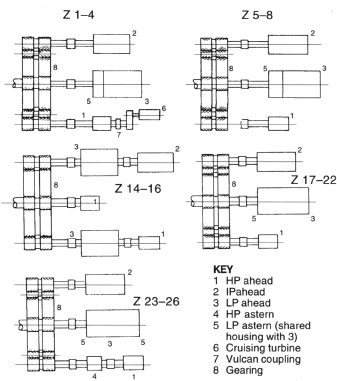
Scheme of turbine arrangements.
From the outset, the OKM laid down the main dimensions for propellers, and Deschimag prepared the workshop designs and submitted them for approval in the usual way. During the further course of development. when Dr W Schmidt became the official responsible for propeller design, the OKM increasingly look over the whole complex affair, evaluating sea trials and experimental work on free-running scaled-down models. Even sketches had 10 be drawn up in a particular manner approved by OKM. The result of this control is that no useful theoretical or practical documentation can be found today in the shipyard archives.
WEIGHTS AND SPACE REQUIREMENTS FOR ENGINE ROOMS (after Witte)

TYPE 1934 ENGINE ROOM (after Witte)

The sets for the first destroyer series were ordered simultaneously and were later discovered to be inadequate or at variance with specifications. A period of experimentation with blade angles and thicknesses led to improvements, and eventually to the final propeller form. In order to avoid the same procedure for the whole series, the optimum diameters and pitch were worked out to establish the most favourable relationships. For Z 1–22 about eight, and for Z 23–44 about six, different sets were trial led before the final design was approved. For the earlier destroyers various turning speeds, to port and starboard, were tested in order to obtain different pitch settings that would enable port and starboard screws to be run at the same revolutions. The reason for the difference proved to be the effect of the stern cool water discharges on the mid-flow, and the openings were modified to permit the same pitch settings for both propellers.
From the beginning, all propellers were manufactured with radially variable pitch, maximum pitch being about half the diameter, gradually decreasing towards the root and tip. The pitch of the first destroyer series was tangentially constant, however. After the discovery in 1940 of French results for the ‘mussel shell’ propellers—so-called for their concave form—a proposal was made lo develop them for German destroyers on the grounds of promising advantages offered by the cavitation effect. A study of the ‘mussel shell’ propellers for Z 17 showed that the initial benefits did not occur until 33.5 knots, contrary to a calculation of 29 knots by Schmidt and Lerbe, but that the type was superior in some respects to the constant or radially variable-pitch propeller. These measures to reduce cavitation led to an improvement in the degree of effectiveness.
The material employed was initially the usual special brass. It was proven in practice and could be poured to make the required form without great difficulty. However, as a result of the shortage of tin. stainless steel was tried. Krupp V2A steel propellors had already been installed on the fast passenger ship Europa, but the material required a special production process because of casting problems. Krupp then developed a steel designated P125 which contained 22 per cent chrome and 7 per cent nickel. This proved more suitable, but manufacture took time—six months as compared to one month for bronze—and was costly. Germania Werft at Kiel and later the Kriegsmarine Werft at Wilhelmshaven ordered special milling machines. In urgent cases it had become necessary meanwhile to turn lo bronze.
The finished stainless steel castings were good. Whether or not they were inferior to bronze—in terms of cavitation and effieiency—is not known, since the circumstances of the time did not allow comparisons.
Towards the end of the war, some destroyer propellers were made of the usual V5M material. All steel propellers for destroyers were cast by Krupp, whereas those in bronze were manufactured principally by Atlas Werke, Zeise. Others came from Blohm & Voss and Germania Werft.
Electrical Plant
A varying number of generators with different outputs supplied the shipboard electricity—turbo-generators for the main current and diesel generators for use when the ships were in harbour. Brief details were as follows:
Types 1934/1934A: Electrical generating stations (E-Werk) Nos 1 and 2 were located in turbine rooms 1 and 2 respectively and had two 200kW turbo-generators each. In Z 1–8, E-Werk 3 was located in compartment VIII, with two 60kW diesel generators and one of 30kW; Z 9–16 had three 50kW diesel sets.
Type 1936: As above, hat with one 40kW and two 80kW diesel generators in E-Werk 3.
Type 1936A: Two generating stations. The turbo-generators produced 200kW each, the four diesels 80kW each.
Type 1936A (Mob): As the foregoing, but with only one 200kW turbo-generator.
Type 1936B (Mob): No details available, but probably as for Type 1936A (Mob).
Other Machinery and Equipment
Besides the maze of pipes and valves of the main engine machinery with its feedwater, heating oil, water coolant and lubricating oil and reserve pumps, many other installations were to be found aboard—the fresh water distillation unit with pumps, the auxiliary boilers with feedwater and heating oil pumps, the water ballast installation, the damage control organisation, including the fire extinguishing installations and auxiliary pump unit with numerous interchangeable pumps: the magazine flooding equipment, the sea water, washing-water and fresh water units with their circulation pumps, and the refrigeration machinery, to mention just a few.
Z 1–22 were fitted with an anti-roll device (an electrically run system based on flooding two trim tanks amidships) which—as also aboard ships up to Panzerschiff size—proved next to useless and were removed during routine overhauls and replaced by stabiliser keels. The exception was Z 20 Karl Galster, which retained the device for experimental purposes. (The unit did not possess any known advantages, but it was kept alive for the benefit of other projects.)
The destroyers had a bow anchor which weighed between 1,850kg and two tonnes. The anchor cable, comprising nine lengths, had a link thickness of from 42mm to 54mm. The cable portside had an additional three reserve lengths

Bunker, tank and trimming plan (from Z 5–8 Sketchbook)
* The steam temperature for the Type 19368 (Mob) was only 426 °C, and it was even lower for the planned Type 1945.