1. Constructional Features
a. GENERAL.
Two features stand out in the construction of Germany Army communications equipment: the unit construction methods employed and the material from which the units are made.
b. UNIT CONSTRUCTION METHODS.
Practically every piece of radio equipment is constructed in units, which are secured to panels and to each other, electrical connections being made by plug and socket strips or by screwing tags or soldering wires to a terminal strip. In most cases this permits quick dismantling for servicing and repair.
c. MATERIALS USED
(1) General.
The metal from which radio sets are made is almost universally an alloy of about 90 per cent magnesium; 8 per cent aluminum; and 2 per cent zinc, copper, and other metals. Each unit consists of a die-casting of this alloy. Not only is the main sub-chassis cast, but also the screening plates, bosses, and recesses for mounting components. The castings are accurately made, requiring little machining, thus establishing excellent mechanical rigidity and improved electrical performance.
(2) Tuning condensers.
Main tuning condensers are made from the standard alloy. Both rotors and stators are machined from a block casting. Thus, there can be no deterioration in performance due to corrosion between individual plates and their mountings.
(3) Insulation.
Extensive use is made of ceramic materials for insulating; they are used for tag strips, tube holders, tube bases, coil formers, and almost universally as the main bearing for ganged condensers. Where coil formers are not made from ceramics, porcelain or pressed bakelised paper is used.
(4) Condensers.
Trimmer condensers are usually either small, air-spaced ones, or of the silvered ceramic-disc type (Philips), which are used to some extent in British and American equipment. Small, fixed condensers are the tubular ceramic type or flat mica type in a bakelite shroud. Except in older versions of the 100 W.S., mica is used sparingly. Larger condensers are paper-dielectric Mansbridge type. No color coding is used, the values being printed on the condenser in mF, pF, or centimeters.
(5) Resistors.
Resistors are usually of the noninductive carbon type, although a few wire-wound ones are employed purely for direct current purposes, such as voltage dividers. No color coding is used, the values being printed on the resistor in ohms.
(6) Coils.
Low frequency coils and chokes are wound with single-strand, enamel-insulated wire, or with silk-covered liztendraht wire. High frequency coils usually are wound with bare copper or copper strip. Alternatively, the coil former has a helical groove in which a thin layer of copper is deposited, apparently by electrolysis. The inductance of most high frequency coils can be varied within small limits by adjustment of a co-axial iron dust core, or copper ring. Intermediate frequency transformers not only have iron dust cores, but are in many cases completely enclosed in an iron dust shrouding.
(7) Tubes.
German radio receivers of modern design have only one type of tube throughout, usually a pentode. These tubes are not always used in an orthodox fashion—for instance a pentode may be used as a diode—but the method considerably facilitates the supply of spares.
2. Power Supplies
Power supplies vary according to the purpose for which the piece of equipment is used. Vehicle sets employ separate rotary converters driven from the 12-volt vehicle storage batteries. These converters are of heavy rugged construction, and therefore remain serviceable for long periods without attention. Ground stations employ storage batteries and dry batteries, pedal operated generators, or small gasoline electric sets. Pack sets employ storage batteries with dry batteries or synchronous vibrators.
3. Simplification
a. CONDENSERS.
Great pains are taken to make the working of the sets as simple and reliable as possible. Tuning condensers are driven through a chain of precision gearing, using fiber and spring-loaded metallic wheels to remove backlash.
b. DIALS.
The dials are of a large size, with calibration spaced over 300 degrees or more. They are accurately marked out, permitting the frequency to be set to very close limits without the use of a wavemeter. Most dials are marked with one or more check points, allowing initial calibration to be accurately set or checked by means of an external or internal crystal oscillator or by means of an internal "glow crystal" (leuchtquarz).
c. NUMBERING.
As an aid to both construction and servicing, each component in a set has a number, and in many cases the wiring is numbered also. Any two points bearing the same number are directly connected.
4. Armored Vehicle Radio Sets
a. GENERAL.
Complete sets in armored vehicles include transmitter, receiver, power units, and accessories, referred to by the designation Fu., followed by a number. An exception is the voice transmitting set Fu. Spr.f. used in self-propelled field and medium artillery vehicles and certain armored cars. This set has no Fu. number. Transmitters and receivers individually are referred to by a description and a letter, such as 10 watt transmitter "c".
b. RADIO SETS USED.
The following tabulation shows what complete radio sets are likely to be installed in various types of armored and self-propelled artillery vehicles. Details on these sets will be found in the accompanying tables.
• Commander's tank: Fu.8 and Fu.5; or Fu.7 and Fu.5.
• Fighting tanks, all types: Fu.5 and Fu.2; or Fu.5 only.
• Assault guns (in armored formations): Fu.5 and Fu.2; or Fu.5 only.
• Armored OP vehicles (artillery): Fu.8 and Fu.4; or Fu.8, Fu.4, and Fu.Spr.f.
• Assault guns (artillery): Fu.8, Fu.16, and Fu. 15; or Fu.16 and Fu.15; or Fu.16 only.
• Self-propelled antitank (light and medium chassis): Fu.8 and Fu.5; or Fu.5 only.
• Self-propelled antitank (heavy chassis): Fu.8 and Fu.5; or Fu.7 and Fu.5; or Fu.5 and Fu.2.
• Antitank-assault guns: Fu.8 and Fu.5; or Fu.5 only.
• Lynx (reconnaissance): Fu.12 and Fu.Spr.f. or Fu.Spr.f. only.
• Antiaircraft tanks (Flak panzer): Fu.5 or Fu.2 only.
• Self-propelled heavy infantry gun: Fu.16 only.
• Wasp and Bumble Bee: Fu.Spr.f. only.
• Armored cars (except eight-wheeled vehicle) and semi-tracked vehicles with armament.: Fu.Spr.f. only.
• Armored cars: Fm.22 and Fu.Spr.f.
• Eight-wheeled armored: Fu.12 and Fu.Spr.f. or Fu.Spr.f. only.
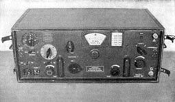
Figure 21.—Short Wave Receiver Kw.E.a.
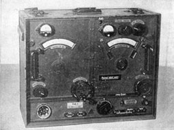
Figure 22.—Radio TFuG. k.
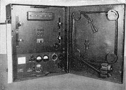
Figure 23.—Relaiskasten T39 Teletype Repeater.
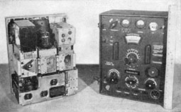
Figure 24.—Transmitter 15 W.S.E.b.
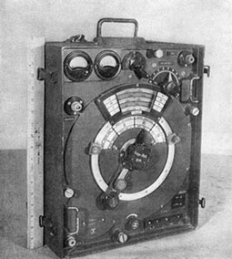
Figure 25.—Transmitter 5 W.S.c.
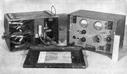
Figure 26.—Feldverstarker with battery case.
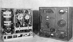
Figure 27.—Transmitter 100 W.
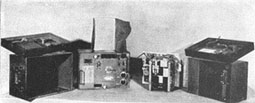
Figure 28.—Attenuator Meter Dampfrugmesser39.
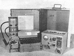
Figure 29.—Feldfernschreiber.
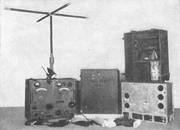
Figure 30.—Transmitter/Receiver(Torn.Fu. bl) with case for battery and accessories.
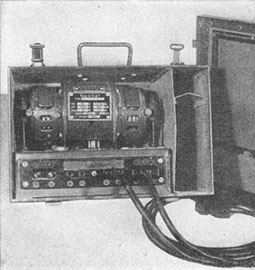
Figure 31.—Dynamotor U5al.
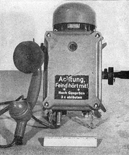
Figure 32.—Fixed emplacement wall telephone.
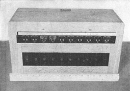
Figure 33.—10-Line switchboard.
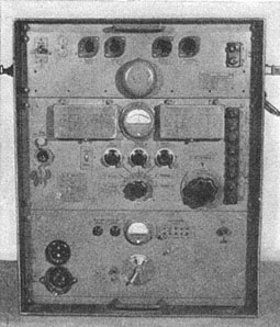
Figure 34.—Teleprinter terminal unit.
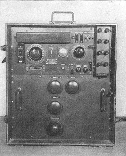
Figure 35.—TFb 1 carrier frequency unit.
Figure 36.—"Spiral-Four" field telephone cable assembly.
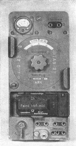
Figure 37.—Torn. Fu. g.
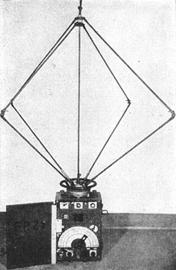
Figure 38.—Direction finding receiver E.P.2a.
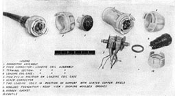
Figure 39.—"Spiral-Four"field telephone cable unassembled.
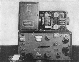
Figure 40.—30W. S. a.
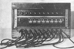
Figure 41.—Field telephone central (10 lines).
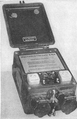
Figure 42.—Vibrator power supply EW.E.
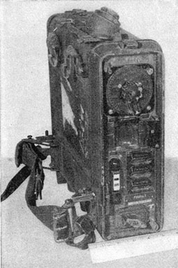
Figure 43.—Walkie Talkie Feldfu.f.
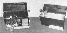
Figure 44.—Fortress emergency transmitter.
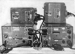
Figure 45.—Receiver Ukw. E.e. Transmitter 10 WS.c.
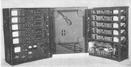
Figure 46.—Leitungsabschluss Kastenline terminal equipment.
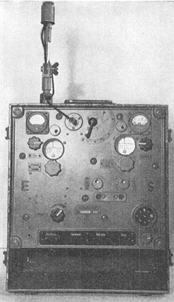
Figure 47.—Two-man packTrans/Receiver (Torn.Fu. d2).
SPECIFICATIONS OF VACUUM TUBES USED IN GERMAN ARMY SIGNAL EQUIPMENT
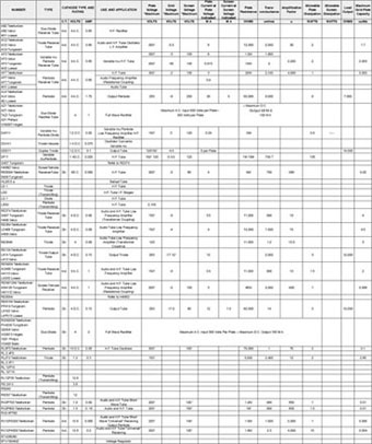
Figure 48.
POWER SUPPLIES FOR GERMAN RADIO SETS
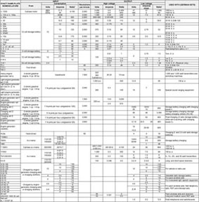
Figure 49.
*For watts column, items marked with an asterisk (*) indicate ampere hours, and are for batteries only.
† Letter T designates German word "TRAGFAHIGKEIT," meaning carrying capacity.
PARTICULARS OF RADIO EQUIPMENT USED IN GERMAN ARMORED VEHICLES, SELF-PROPELLED ARTILLERY AND ARMORED HALF-TRACKED VEHICLES
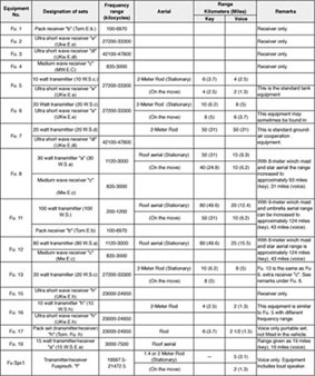
Figure 50.
DETAILED DESCRIPTION OF GERMAN ARMY LINE COMMUNICATION EQUIPMENT INCLUDING FIELD TELEPHONES AND SWITCHBOARDS
Field Telephone 33
• Dimensions and weight: 8.5"x11x4"—12 lbs
• Description: This general purpose telephone for local battery operation only, with magneto system for calling, is equipped with magneto system. Provision is made for extra plug in headphones and testing of line and bell circuits, and two jacks connected in parallel with line circuit for connection as exchange. It can be connected to a post office exchange by a special adaptor. The power supply is 1.5 volts; either inert or dry cells may be used.
• Remarks: The instrument case is a bakelite moulding approximately 0.2 inch thick. The lid has a self locking fastener which is pressed to open. The shoulder strap has a hook on it from which the telephone head set can be hung if required operation of the instrument is conventional.
The German Wall Telephone for Field Emplacements.
• Dimensions and weight: 15"x7 1/4"x5 1/2"
• Description: A telephone of extremely sturdy construction and used apparently where moisture and vibration are excessive. These telephones are local battery operated, mounted on concrete walls, and interconnected through ducts. The telephone is of heavy waterproof construction and the handset is connected to the main assembly by a heavy rubber-covered waterproof cord. The receiver is covered with a rubber earpiece. Both the main assembly case and the handset frame cover plate is fastened by means of 4 bolts with triangular shaped heads recessed in each corner of the face. This case plate is attached to the body by chains to prevent its falling off when loosened.
• Remarks: The ringing generator of this set is the same type as that employed in the field telephone 33; may be employed by Allied troops in locations where its qualities are desirable.
Endverstarker (f. Feldfernsprecher 33) (Terminal Amplifier for Field Telephone 33)
• Dimensions and weight: 9"x7 3/4"x4 1/4" A.C. Set, 8 1/2"x6 1/2"x3 1/2" Battery Set
• Description: AC powered unit: This is an audio-frequency amplifier employing one triode tube, type RE 084. The receiver circuit of the field telephone 33 is opened and the incoming signal is fed to the grid of the amplifier. The amplified signal is returned to the earphone receiver. Power is supplied through a transformer, having high and low voltage windings for plate and filament supplies. The plate supply is rectified (half-wave) by rectifier GLo and the filament supply by a full wave rectifier GL1.
• Battery operated unit: The principle of operation is very nearly the same.
• Remarks: This piece of equipment is an audio-frequency amplifier to increase the range operation of field telephone 33. They may be either powered by AC or by batteries. These sets are employed in place of, or in conjunction with field repeaters. When using the AC set, the handset of the field telephone 33 is used, but with the battery set there is already one provided.
Line Intercept Receiver LE. 35.
• Dimensions and weight: 17 1/2"x 13 1/2"x11"—78 lbs.
• Description: Provision for tapping to several telephone or telegraph lines and monitoring any one required. No Contact need be made as a loop brought to within a foot of the line may be sufficient. The equipment can be used to pick up earth currents between two earthed lines. The amplifier consists of a three-stage resistance capacity coupled circuit using three pentodes, all RV2 P800's. The amplifier has a gain of 72 db. Three fillers are incorporated in the set:
Storsieb: a special filter for alternating the odd harmonics of 50 cycles where main interference reduces intelligibility.
A band-pass filter normally in circuit.
Additional filter sections which reduce the band filter to 400 c/s-2200 c/s.
• Remarks: A portable line intercept amplifier, complete with batteries; may be either manpack or vehicle.
10-Line Exchange
• Dimensions and weight: 8"x14"x6"—20 lbs.
• Description: The exchange will take up to 10 single or double line circuits. In case of mixed circuits (double and single lines to exchange) where the double lines are numerically superior, the single wire circuits should be connected via a cordless transformer, or vice versa if single lines preponderate. Subscribers lines may be connected either direct to the terminals 1 a.b. to 10 a.b. on top of the exchange or through a connection rack; or via 30-way plug and line system to a line terminal unit.
• Remarks: The exchange is roughly comparable with the British 10-line U.C. switchboard, although it is smaller and more compact.
German 10 Line Cordless Exchange (Exact German Nomenclature unknown)
• Dimensions and weight: 9 1/2"x17 1/2"x7 1/2"—
• Description: This set was designed for common battery operation, the line terminals being marked negative and positive, but may be used for local battery operation. It accommodates 9 lines besides operator's phone and can handle only two conversations at one time. Provision for night alarm circuit has also been made. Toggle switches for cross connection of the subscribers are utilized in conjunction with line drops which are located about the keys. May be paralleled with similar type of exchange.
• Remarks: Is well made, easy to use and maintain, but has the disadvantage of being unable to accommodate more than two calls at one time, though ideal for conference calls.
Small telephone exchange Box (Vermittlungskästchen)
• Dimensions and weight: 4"x4"x1 1/2"
• Description: One line switchboard unit with an attachable visual indicator used with other such units to serve from two to ten or more telephone subscribers.
• Remarks: The set is well built and sturdy. Its simplicity and portability are outstanding characteristics.
The small fortress switchboard OB 36 (Kleine Festungsvermittlung)
• Dimensions and weight: 48"x39"x8"—
• Description: The switchboard is extremely heavy and housed in a cast iron box; brackets are provided at the back of the box for fastening the switchboard on a wall. Can accommodate 30 lines and 12 interconnections are possible. Provision has been made for connecting ten of the 30 lines on the OB 36 to common battery trunks. (Lines 21 to 30 being fitted with a 4 mfd condenser).
• Remarks: Because of its weight and size obviously could only be used in fixed installations. Is very similar to the OB 37 with the exception of two principle differences in circuit.
Large Field Switchboard for 60 lines
• Description: This is made up of three types of standard sections combined in multiple until desired size is reached. Is designed for local battery operation with ground return or metallic circuit. By adding a commercial adapter, connections may be established with civil exchanges using C.B. or automatic dial system. Is made up of 4 sections: (1) assembly "A" including plug cord holders and conference jack panel, (2) answering jack panel unit (ten jacks), (3) conference call panel, (4) adapter for use with automatic dial exchange.
• Remarks: With the use of multiple jack field this board can be built up to 300 lines. Knowing this, whether the term 60-line switchboard is applicable as a separate piece of equipment is a matter for further consideration.
DETAILED DESCRIPTION OF GERMAN ARMY LINE COMMUNICATIONS EQUIPMENT INCLUDING SWITCHBOARDS AND KINDRED EQUIPMENT
10-300 Line Switchboard
• Dimensions and weight:
Operating Unit: 9 1/2"x13"x21 1/2"—52 lbs.
10 Line Unit: 4 1/2"x13"x7" —11 lbs.
50 Line Unit: 15 1/2"x13"x7" —37 lbs.
100 Line Unit: 15 1/2"x13"x7" —31 lbs.
150 Line Unit: 15 1/2"x13"x7" —27 lbs.
Bunching Unit: 2 1/2"x13"x7" — 5 lbs.
Dialing Unit: 7"x13"x7" —12 lbs.
Superimposing Unit: 7 1/2"x13"x7" —21 lbs.
• Description: The apparatus consists of several units built up to form the whole exchange: the operating unit, 10-line answering unit, 50-line answering unit, 100-line multiple unit, 150-line multiple unit, 10-jack bunching unit, dialing unit, and superimposing unit. Line connections are made at the rear of each unit by a 30-way connector with a 30-pin plug at each end. The drop-flap indicators are automatically restored when the associated jack has a plug inserted. A night alarm is also provided.
• Remarks: Very neat, light and compact, probably used in line of communication formations.
Teleprinter Terminal Unit Incorporating Single Channel V.F. Equipment. (Springschreibanscklussgerat)
• Dimensions and weight: 24"x21"x9 1/2"—93 lbs.
• Description: The terminal unit and teleprinter are operated from 110-220 volts AC (total consumption 150 watts). Provides for single and double current working (simplex or duplex) and remote control operation. (VF working.) Intercommunication between teleprinter and similar equipment over a line or radio link.
• Remarks: Used in line of communication companies.
Teleprinter Terminal Unit Incorporating Single Channel V. F. Equipment. (Springschreibanschlussgerat)
• Dimensions and weight: 24"x21"x9 1/2"—96 lbs.
• Description: This is for simple working only and operates on the same type of power supply as above.
• Remarks: Both types can be worked with American and British teleprinter with the inclusion of their respective T.T. Units. For line of communication purposes.
Telewriter Tbs/24a-32
• Dimensions and weight: 17 1/2"x15 1/2"x9 1/2"—57 lbs.
• Description: Sends figures 1 to 9 and 0, the characters+, -, /, ?. and the 26 letters of the alphabet. Works directly into a telephone line. Field telephone can be plugged in for speech working. A 900-cycles filter can be switched in to reduce interference. When the interference is too great, 900/c/s morse code can be sent and received on headphones. 12-pt socket on panel is for connection to radio set through an intermediate unit. Tube system 900 c/s sender oscillator—Rec amplifier—Rec rectifier speed control. All tubes are type RV12P400. Power supply 12-volt storage battery to motor, coupled to dynamo for H.T. for tube.
• Remarks: The mechanism of the set is simple but precision made, and the keyboard is continental type.
Telewriter Tbs/T 36 L.O. (Tape Teleprinter) Fernschreiber
• Dimensions and weight: 20"x16 1/2"x12"—63 1/2 lbs.
• Description: The receiving and transmitting mechanisms are similar to those in the American Teletype machine described in detail in the Teletype Manual No. 11. All cables are permanently attached to the teleprinter. Schematic and wiring diagrams will be found mounted on the meter base plate.
• Remarks: Associated equipment T.T.U., e.g. (Springsckreibarschussgerat).
Speech Scrambler 9K III b.
• Dimensions and weight: 17"x13"x9" (approx.) —70 lbs.
• Description: These are used to provide two-way security on a wire or radio-telephone circuit. It is powered by a 2-volt storage battery and one, 90-volt dry battery. The set is compactly built and is very sturdy in construction. The individual circuit components are separated according to their functions and completely screened. 3RV2P800 are used. Two of these are used as audio amplifiers, one on each side of the two-way circuit. The other is used as a 2000-cycle audio-oscillator. If not required the scrambler circuit may be switched on and the input and output circuits directly connected.
• Remarks: Use for security purposes over telephone lines. Is portable and can be carried by 1 man.
Tonschreiber Models b and b1
• Description: Both models with the exception of one employing a synchronous speed control system are identical. They are divided physically into two sub units known respectively as the Lanfwerke and the Verstarker. It offers the facility of recording an audio signal on a magnetic ribbon. During the recording process, the quality and ware of the signal impressed on the tape may be monitored. Provision has also been made for playback and for rewinding and wiping the tape used. This recording tape is made of paper; one side of it has been covered with a coating of material having high magnetic properties. The apparatus was designed to be supplied from AC mains. DC cannot be used. While the voltage may vary from 110 to 250 volts the permissible frequency variation is not known.
• Remarks: High speed recording apparatus. The Germans have designed and manufactured a series of magnetic tape recorders. There are in existence 2 other models known; they are: the Tonschreiber c which is a spring-driven recorder for rough field use; and the AEG Type K4, which is a studio type device.
German Teleprinter SWBD (T39) Vetmitttungssckrank
• Dimensions and weight: 21"x18 1/2"x8 3/4"—50 lbs.
• Description: This teletypewriter switchboard is housed in a metal cabinet with folding tubular legs. It has four pairs of cords for handling simultaneous complete circuits and provisions for terminating one to ten teletypewriters. The construction is rugged and will withstand considerable abuse, although it is not moisture proof; the wiring is neat and sturdy. The answering and calling cords are each coiled on an individual wound reel. This method of storing excess cord lengths is same as that employed on the German 20-line, local battery telephone switchboard.
• Remarks: Line of communication companies.
German SWBD. 20 line.
German Relaiskasten T39. Teletype Repeater.
Leitungsabschlusskasten (Line Terminal Equipment)
PERFORMANCE CHARACTERISTICS AND SPECIFICATIONS OF TWO-WAY RADIO SETS USED IN THE GERMAN ARMY GROUND FORCES
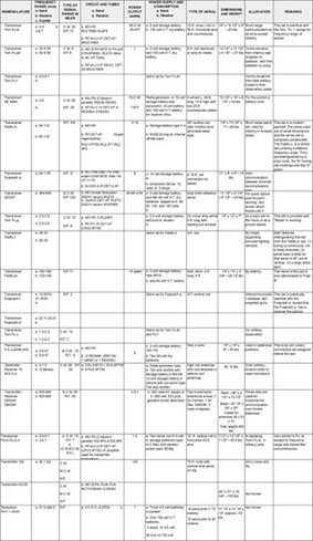
Figure 53.
PERFORMANCE CHARACTERISTICS AND SPECIFICATIONS FOR GERMAN GROUND RADIO TRANSMITTERS
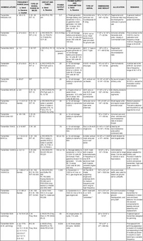
Figure 54
PERFORMANCE CHARACTERISTICS FOR RADIO TRANSMITTERS USED AS GERMAN ARMY MESSAGE CARRIER EQUIPMENT
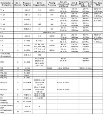
Figure 55.
LINE EQUIPMENT—German Carrier Equipment (Army and Commercial)
The German carrier equipment, both commercial and army is listed above. It is similar to the American in design, channel frequencies, and use.
Within the German army the most common are apparently more recent additions. sets for field use are the Tragerfrequenzgerat a (Tf.a.) and the Tragerfrequenzgerat b (T.f.b), including b1, b2, b3, and b4. Other sets n use by the Germans are: Mehrfach (MEK) MG, MK, T1, T3, E1, E2, and E3; the MG and MEK carrier systems are apparently more recent additions.
The "L" and "U"carrier systems for cable, are used by the German PO. The "L" system is installed on lightly loaded cable, and the "U" or non-loaded cable. The German broadcasting carrier system is the Tragerfrequenzgerat Rundfunk (TfR)—"Carries Broadcasting.".
Differentiation is made with multiple Tf (carrier) systems between single channel systems (transmission channels for EW and WE traffic lie directly next to one another, as in the case of sets T.f.a. and T.f.b.) and group systems (the channels for each carrier direction are adjacent and they form therefore, two separate groups, e.g. sets MEDK and MG).
Abbreviations and Nomenclature:—
a. Carries Equipment:—
1. T.f. (a or b), Tragerfrequenzgerat, Carrier Frequency Set.
2. MEK., Mehrfach-Einzelkanal, Multiple Channel.
3. T.f.R., Tragerfrequenz Rundfunk, Carrier Frequency Broadcasting.
4. E (1, 2, 3); T (1, 3); MG; M (1-7); MK EK; L; U:—Meanings not known.
On the chart above, kilometers are converted to miles and nepers (standard German power level unit) to decibels.
1 neper equals 8.6858 decibels.
1 decibel equals 0.11513 nepers
PERFORMANCE CHARACTERISTICS AND SPECIFICATIONS FOR GERMAN INTERCEPT GENERAL PURPOSE, AND SPECIAL PURPOSE RADIO RECEIVERS
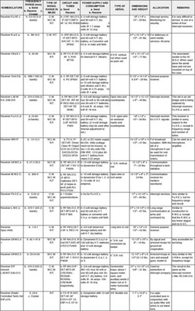
Figure 56
PERFORMANCE CHARACTERISTICS AND SPECIFICATIONS OF TWO-WAY RADIOS AND EMERGENCY TRANSMITTERS USED IN GERMAN AIRCRAFT
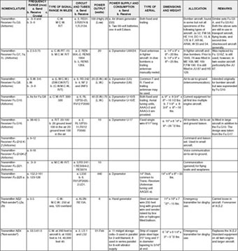
Figure 57
PERFORMANCE CHARACTERISTICS AND SPECIFICATIONS OF RADIO EQUIPMENT INSTALLED IN GERMAN AIRCRAFT FOR DIRECTION FINDING, BLIND LANDING, BLIND BOMBING AND HEIGHT FINDING
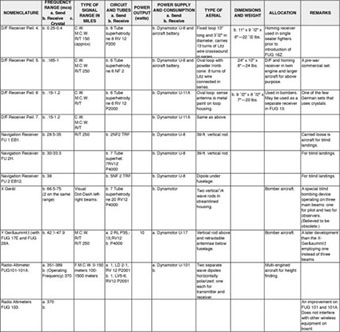
Figure 58
GERMAN CABLES
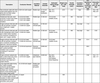
Figure 59.
DESCRIPTION OF EQUIPMENT USED IN THE GERMAN ARMY FOR TESTING RADIO SETS
Wavemeter Fremes a.
• Dimensions and weight: 17 1/2"x14"x10"—46 lbs.
• Description: Frequency range: —30 kcs —30 mcs in 20 switched bands. Facilities: will emit modulated or unmodulated signal. (Loose or tight coupling to receiver.) Circuit as receiver: RF-oscillating detector—2AF RES 094. RE134W: RE. 134. Circuit as sender: oscillator—anode modulator. Power supply: 4-volt storage battery. 3-volt grid bias, 150-volt H.T. batteries.
• Remarks: The outstanding feature in the construction of the wave-meter is the massive turret for waveband switching, which takes up most of the space inside the case.
Frequency Tester F. pruf. dl.
• Dimensions and weight:—29 lbs.
• Description: Frequency range —120 —156 mc (26 fixed frequencies). Power supply: storage battery 2 N/9 and one 90-volt H.T. Battery.
• Remarks: For frequency calibration of fixed sets within its range.
Field Test Set 18 (Das Feldmesskastchen)
• Dimensions and weight: 6.3"x4.7"x2.9"—2 3/4 lbs.
• Description: A field test set similar to the U.S. army's EE65.
• Remarks: A general purpose field Test Set.
Attenuation Meter.—39 (Dampfungsmesser 39)
• Description: Is capable of measuring the amplification (in nepers) of 2 and 4 wire repeaters and the attenuation at 300 cycles over any type of line. Can measure crosstalk attenuation between the lines. Is powered with 90-volt H.T. battery and a 2-volt 2B19 storage battery.
• Remarks: Used in conjunction with telephone repeaters in testing and adjusting input and output levels.
German Tube Checker (Rohrenprufgerat RPG4)
• Dimensions and weight: 16"x15"x9"—30 lbs.
• Will test all European and a small number of American tubes. It may be used as a milliammeter, ohmeter, and capacity meter. Can only be used for DC voltages and currents.
German Exploring Coil
• Description: This apparatus can be used to locate grounds, shorts, crosses and wet spots in cables. (However, it will not locate "opens" in cable pairs.)
German Frequency Test Set F. prufg. f.
• Dimensions and weight:—25 lbs.
• Description: Crystal controlled oscillator fundamental output frequency of 26 mcs. Power supply: 2.4-volt storage battery for vibrator, one tube RL2 4T1. Consumption: 2.42 @ 6 amperes.
• Remarks: A field pack servicing and calibration unit for the Feldfu. b and c.