
1. Instruments
a. GENERAL.
In general the instruments used in the field by the engineers of the German Army are identical with our own, particularly their transits, theodolites, and surveyor's levels. The main differences occur in compasses and gap-measuring instruments.
b. GERMAN FIELD COMPASS (Marschkompass).
(1) Description.
The German field compass is a black, pocket-sized instrument. The housing is of aluminum-like metal. A brass outer ring is attached with a carrying handle. A hinged, linear, centimeter scale unfolds from the base of the compass housing. The letters MKZ(KZ) are marked on the body of the compass.
(2) Operation.
The swinging of the magnetic needle can be stopped by pressing the damper button. When the destination is visible, open the cover and raise the mirror half way, so the magnetic needle can be seen clearly. Sight the point through the rear V sight and the front aperture at the base of the mirror. Hold steady until the point is in line with the eye, then with the free hand turn the azimuth circle until the magnetic needle falls on the magnetic declination mark. Read the azimuth from the dial. The German compass is numbered counter-clockwise, and the graduations are in mils. To simplify compass reading, the dial has been abbreviated so the last two zeros have been omitted; thus, 6,000 mils is shown as 60. The markings for directions are the same as our own, with the exception of East which is marked "O" for Ost. The adjustments for magnetic declination are marked directly on the azimuth dial; two luminous dots indicate 150 mils East and West.
c. NEW TYPE FIELD COMPASS (Marschkompass "A").
It is now known that a new type compass is in use in the German Army. This compass is numbered clockwise in mils.
d. GAP-MEASURING INSTRUMENT.
This is a simple device to measure the width of streams and similar gaps. It is designed on the principle of similar right-angled triangles and consists of two parts: a fixed mirror and a measuring mirror.
2. German Demolition Equipment
a. SAFETY FUZE BLASTING CAP AND ACCESSORIES (Sprengkapsel No. 8).
(1) Description.
This blasting cap is similar to the U.S. and British types. It is designed to fit over the safety fuze and be initiated by it. The initiator of the cap consists of lead azide and lead styphnate.
(2) Characteristics.
• Length: 2.36 inches.
• Diameter: 0.28 inch.
• Packing: 15 in wooden box.
(3) Bakelite Holder (Zünderhälter).
This holder serves the double purpose of connecting the cap and fuze and permitting the cap to be screwed into the charge. It consists of a tube which covers the junction of the cap and fuze, and is enclosed in a bakelite cover. At one end of this cover is an externally threaded sleeve; the other end is covered by a bakelite cap with a central hole for passage of the fuze.
(4) Blasting Cap Igniter Set (Sprengkapselzünder).
This is a prepared set with a cap in a bakelite holder, with a 3- to 6-foot safety fuze attached, and a safety fuze igniter. This provides a convenient short-delay demolition igniter.
b. SAFETY FUZE (Zeitzündschnur).
The black powder train of this fuze is enclosed in strands of jute-like fibre and white cotton-like fibre alternately, the whole being covered with a bituminous paint, over which goes the black rubber outer covering. This safety fuze burns in air or under water at the rate of approximately 2 feet a minute. It can be initiated in the same way as U.S. and British safety fuzes.
c. ELECTRIC BLASTING CAPS.
(1) Glühzünder 28.
This consists of a cap, with twin leads of copper or iron, and a wire bridge. The whole fits into a standard bakelite cap holder. The copper leads have a resistance of 2 ohms; iron, 3 ohms.
(2) Delay Electric Blasting Cap (Glühzünder mit Verzögerung).
These electric caps, which fire with a delay of 2, 4, 6, 8, or 10 seconds after electrical initiation, are similar to ordinary electric caps except that there is a pyrotechnic delay pellet between the wire bridge and the cap proper. These caps have the number of seconds delay marked on a disc attached to the leads.
(3) Spark Gap Electric Blasting Cap (Spaltzünder)
In these caps, the wire bridge has been replaced by a spark gap.
d. INSTANTANEOUS FUZE (Knallzündschur).
This fuze has a soft, pliable, green, outer covering with a waterproof varnish finish, surrounding an explosive core. It will detonate under water, initiated by a cap, but the ends must be waterproofed.
e. 100-GRAM CARTRIDGE (Bohrpatrone 28).
There are two types of this cartridge; one in waxed paper, and one in compressed paper. Both cartridges may be marked Bohr-Patr. 28, identifying the cartridge, and Fp.02 or Grf.88, identifying the explosive as TNT or picric acid.
f. 200-GRAM SLAB (Sprengkoerper 38).
This slab is provided in two forms: in waxed paper and in a bakelite case. The waxed paper slab may contain either TNT or picric acid. Pressed picric acid is contained in the casing of two bakelite mouldings. The bakelite slab actually weighs 250 grams or 8 3/4 ounces.
g. 1-KILOGRAM (2.2 POUNDS) SLAB (Sprengbüchse 24).
(1) Description.
This slab may be made either of TNT or picric acid, in a pressure-resisting zinc container which permits it to be used at any depth of water. There are three sockets for standard caps and holders, or igniters —one on each face of the slab, excluding the base. Each socket is covered with a paper disc marked Sprengbüchse 24 and either Fp.02 (TNT) or Grf.88 (picric acid).
(2) Characteristics.
• Weight: 2.2 inches
• Length: 7.9 inches
• Width: 2.9 inches
• Thickness: 2.2 inches.
h. 3-KILOGRAM (6.6 POUNDS) SLAB (Geballte Ladung 3 Kg.).
(1) Description.
This slab, in a zinc container with a carrying handle at one end, has either three or five sockets for standard caps and holders or igniters. The container is pressure-resisting, and the slab may be used under any depth of water. This slab is often used with igniters for improvised mines. It is marked 3 Kg. on the side.
(2) Characteristics.
• Weight: 6.6 pounds.
• Height: 7.7 inches.
• Width: 6.5 inches.
• Thickness: 3 inches.
i. 3-KILOGRAM BALL CHARGE.
(1) Description.
The spherical body of the charge is constructed in two hemispherical sections of pressed mild steel, seamed together by a rolled joint. The securing lugs are welded to the top half of the body, and to them are attached the two ends of a canvas carrying strap. The charge has the standard threaded igniter socket and is marked 3. Kg.
(2) Characteristics.
• Weight of explosive: 6.6 pounds.
• Diameter: 6.25 inches.
• Filling: Amatol
j. HOLLOW DEMOLITION CHARGE (400 GRAMS OR 14 OUNCES).
This charge is a cup-shaped, aluminum case, painted field gray, with the standard threaded cap socket in the top. A plate is recessed into the base. The central part of this plate forms a hemispherical wall surrounding the hollow space in the base of the charge. The main filling is penthrite.
k. 12.5-KILOGRAM HOLLOW CHARGE (Hohlladung).
(1) Description.
This charge is designed to blast holes in steel plates in permanent fortifications or for special tasks. It is enclosed in a sheet iron cover with a carrying handle. In the base of the charge is a hemispherical cavity, and in the top is a standard threaded cap socket. This charge is usually part of the equipment of airborne troops.
(2) Characteristics.
Outside diameter: 11 inches.
Diameter of cavity: 5.3 inches.
Weight: 28 pounds.
Filling: TNT.
l. 13.5-KILOGRAM HOLLOW CHARGE (Hohlladung).
(1) Description.
This hollow charge rests on three telescopic legs, which ensure proper "stand-off". The charge is provided with a pellet contained in a standard detonator socket.
(2) Characteristics.
• Outside diameter: 13 1/2 inches.
• Diameter of cavity: 9 3/4 inches.
• Weight of charge: 30 pounds.
• Filling (RDX-TNT): 21 pounds.
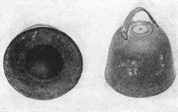
Figure 61.—Hohlladung 12.5-kg Demolition Charge.
m. 50-Kilogram Hollow Charge (Hohlladung).
(1) Description.
For convenience in transport, this charge is made in two parts. The lower part, which is provided with a separate carrying handle, contains a hemispherical cavity. The upper part contains both an explosive charge and a standard cap socket. This charge is part of the equipment of airborne troops.
(2) Characteristics.
• Outside diameter: 20 inches.
• Diameter of cavity: 8 inches.
• Height of cavity: 4 inches.
• Weight of charge: 110 pounds.
• Filling: TNT.

Figure 62.—Hohlladung 13.5-kg Demolition Charge
(Top: showing hemispherical cavity and stand-off legs in collapsed position. Bottom: in firing position).
n. HOLLOW RING CHARGES (Hohlringladung).
(1) Description.
These charges, used principally for the destruction of gun barrels, contain TNT, in a thin annular metal casing which is slipped over the gun barrel and fired by a cap. There is an annular, hollow space of semi-circular cross section on the inside of the ring designed to increase the cutting effect. The flag-mentation effect of these charges is negligible, which makes them suitable for use by raiding parties and patrols.
(2) Characteristics.
Hollow ring charge for antitank and machine-gun barrels:
• Weight: 2 pounds 11 ounces.
• Outside diameter: 7.1 inches.
• Inside diameter: 3.9 inches.
• Width: 3.1 inches.
Hollow ring charge for field guns:
• Weight: 7 pounds 1 ounces.
• Outside diameter: 10.4 inches.
• Inside diameter: 6.7 inches.
• Width: 3.4 inches.

Figure 63.—Shaped Demolition Charge (50 kg).
o. BANGALORE TORPEDO (Gestreckte Ladung).
This torpedo is made up of units of 16-gauge steel pipe lengths, with a sleeve welded to one end to form a socket for the adjoining unit. Units are packed with blasting gelatine or other suitable explosives. Detonating fuzes run the lengths of the tubes. The torpedo is initiated at one end by two independent caps, using a cap igniter set for one and a length of safety fuze and match for the other. Other sections carry a cap fitted to the end of the tube. When assembling sections, the free end of the fuze at the socket end of one section is tied to the cap at the spigot end of the next section.

Figure 64.—Bangalore torpedo.
p. GERMAN FIELD EXPLODERS.
(1) Exploder 1942, six-barrelled (Nebelwerfer).
This exploder is 6 inches high and has two sockets in the core. One socket is for winding, and the other for a seven-pin plug providing six circuits with a common central return. On the outside of each of the six outer plug holes are six numbered windows which glow in turn as their circuit is completed. The exploder thus can fire six circuits rapidly, one after another; the operator can see the glow lamps recording the firing in succession. Since this exploder has a low capacity, with 20 detonators the maximum number it will handle, its use for demolitions is restricted.

Figure 65.—Exploder 43 (6-barreled).
(2) Small Exploder 1940 (Glühzündapparat 40).
This exploder forms part of the portable demolition kit (Zündgerät 40). It is 5.3 inches high and has an oval-shaped top, mounting the firing terminals and the winding socket. It will fire through 90 ohms external resistance, and the generator is turned directly by the handle in the winding socket. Only when the maximum current is generated is the circuit closed; for firing, the handle must be turned as fast as possible to the "stop". The exploder has an internal resistance of 30 ohms and generates a current of 1 ampere at 80 volts. Before using the exploder, it must be tested with a special neon test tube, which not only tests the exploder but also excites the magnetism in the generator.

Figure 66 — Exploder 39 (Glühzündapparat 39).
(3) Field Exploder 1939 (Glühzündapparat 39).
This exploder is packed in a leather carrying case. It fires through a maximum resistance of 300 ohms and has an internal resistance of 40 ohms. The winding key is kept in the carrying case, which also holds the test resistance, a spare spring, and a screw driver. On the top of the exploder are the winding socket, the spring socket, and the spring terminals.

Figure 67.—Exploder 37 (Glühzündapparat 37).
(4) Field Exploder 1937 (Glühzündapparat 37).
This exploder generates 300 volts and fires through a maximum resistance of 300 ohms. The internal resistance is 43 ohms. The exploder has a winding key kept in the carrying case, which also holds the test resistance. On top of the exploder is a winding socket marked Aufziehen and a firing socket marked Zünden. The firing terminals are on an insulated step below the level of the cover. The spring driving the generator cannot be released unless it has been fully wound. To use the exploder, wind the spring clockwise until the "stop" is reached. To fire, turn the socket marked "Zünden" with the key.

Figure 68.—Exploder 26 (Glühzündapparat 26).
(5) Field Exploder 1926.
This exploder weighs 14.5 pounds and is packed in a leather case. The exploder is of the low tension type (hot wire as opposed to spark) with an internal resistance of 45 ohms. Maximum resistance through which it will fire is 255 ohms.
q. PORTABLE DEMOLITION KIT 1940.
This is a pack containing everything needed to fire charges electrically. It weighs 51 pounds, and can be carried by a handle or by shoulder straps on the back. It contains a small exploder (1940) and neon test tube, a continuity tester (galvanometer) (1926), 40 electric detonators, two spools of single cable and two drums of double cable, metal sleeve for crimping over electrical joints, a notched pocket knife, crimpers, and insulating tape.
r. CONTINUITY TEST (GALVANOMETER) 1926.
This tester not only tests continuity but also measures resistance of circuits and detonators. It contains an ohmeter, resistance, and battery (1.5 volts). The battery is housed in a cylinder 4.7 inches high with the ohmeter on top. Adjusting screws for setting the ohmeter needle to zero and infinity are midway between the testing terminals. A built-in resistance protects caps from being initiated while being tested for continuity.
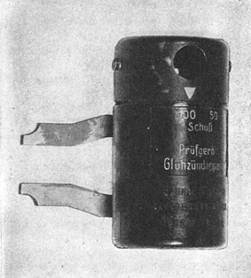
Figure 69.—Resistance and neon test lamp.
s. TEST RESISTANCE AND NEON LAMPS.
The resistance is for testing the Field Exploder 1926 for firing through 250 ohms resistance. The neon lamp, designed for testing the Field Exploder 1937 and 1939, has a screw head which may be set to test for firing either 50 or 100 detonators. There is another neon lamp for testing the small Exploder 1940. It is part of portable Demolition Kit 1940.
t. MAGNETIC DEMOLITION CHARGE ANTITANK (Panzerhandmine).
This charge is spherical and completely covered by pressed cardboard. This cardboard casing, held in shape by two metal bands, extends 4 inches below the base of the explosive. Primarily designed as a demolition charge, it also can be used against tanks. The explosive filler is 1 pound 12 ounces of cyclonite and TNT. The booster consists of two pellets of cyclonite and wax in which there is a fitting for a standard igniter of the BZ type.
u. GERMAN ANTITANK MAGNETIC HOLLOW CHARGE.
This charge is painted field gray. The three attached magnets are strong enough to hold the charge against a vertical surface. The main filling is in a pressed metal container, conical in shape, with an elongated apex to act as a hand grip and to accommodate the detonator. The igniter has a delay of only seconds. However, a new type igniter with a yellow head and a 7 1/2-second delay has been introduced.
3. Booby Traps
a. MATERIALS.
The following standard materials have been used in German booby traps:
• Tellermines.S-Mines.
• C.V.P.I. Mines.
• Improvised wooden mines.
• Prepared charges.
• Mortar bombs.
• Hand grenades.
• Italian B.4 mines.
• Italian hand grenades.
• French antitank mines.
• British G.S. mines Mks. II, IV, and V.
• British gun cotton slabs.
• British aircraft bombs.
b. METHODS OF SETTING.
The booby traps are set ordinarily in the following ways:
• Tellermines with anti-lifting devices.
• Tellermines connected by prima cord to two or more E.P. mines and fitted with an anti-lifting device.S-Mines with pull igniters.
• C.V.P.I. mines with setting at "K" and a trip or pull wire.
• Prepared charges, concealed in rubbish, fitted with pull igniters and pull wires.
• Charges inside a water bottle fitted with a pull igniter to detonate on the withdrawal of the cork.
• Mortar bombs fitted with S.Mi.Z.35 igniter.
• Egg and stick grenades fitted with pull igniters.
• Italian B.4 mines with trip wires.
• French antitank mines with pull igniters.
• British aircraft bombs with pull igniters and trip wires.
• Empty German mine cases with pull igniters attached to the bottom of the crate or inside of the lid.
c. EMPLOYMENT IN BUILDINGS.
Pull igniters inserted in prepared charges, grenades, and standard mines commonly are used as booby traps in buildings. The friction igniter ZDSCHN.ANZ.29, attached to a prepared detonator, also is used with a pull cord. The trip or pull wires may be laid across entrances and doorways, across stairways, or attached to doors of rooms, cupboards, or to windows. Both ends of wires should be investigated for traps. If wires are in tension, they must not be cut until this investigation has been carried out. Pressure igniters commonly are found under loose boards and door mats. The DZ.35 type is the igniter usually employed.
4. German Mine Detectors
a. MINE DETECTING ROD, 1939 PATTERN.
(1) Description.
This detector consists of a length of light alloy tubing, one end of which carries a steel point, while the other carries a bayonet joint permitting a second length of tubing to be added when the operator is standing. The weight of the main tube and point is approximately 10 ounces.
(2) Employment.
This detector is used as a probe, the point being dropped vertically into the ground from a height of about 4 inches. It is claimed that the nature of any underground object encountered can be recognized by the characteristic sound coming from the tube.
b. MINE DETECTOR BERLIN 40 TYPE B.
(1) Description.
This detector consists of a detector unit carried in a pack on the operator's back, a search coil, sectionalized pole, headphones, and cable connections.
(2) Employment.
The variable condenser is adjusted to produce a suitable note in the earphones. Proximity of a metal object to the search coil produces a change of tone.
c. MINE DETECTOR Tempelhof 41.
(1) Description.
This is a portable detector provided with a loud speaker instead of earphones. The whole instrument can be carried in an infantry pack.
(2) Employment.
The tone control is turned to the right until the loudspeaker produces its maximum volume. In presence of a metal object the tone will rise in pitch.
d. MINE DETECTOR Frankfurt 40.
(1) Description.
This detector is contained in a wooden box which fits into a canvas pack. The pack also has a compartment in which the search coil can be carried when not in use. The box is divided into two compartments, one for the batteries and one for the detector. The wiring is exposed by removal of a sliding panel which is held in position by one screw. The tubes and batteries are accessible after removal of the front panel. The pole is in three sections. The search coil is housed in a bakelite moulding.
(2) Employment.
The circuit is adjusted for zero balance. A tone is produced in the earphones by proximity of a metal object.
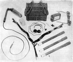
Figure 70. Mine Detector (Wien 41).
e. OTHER MINE DETECTORS.
Other mine detectors in general use are:
• Pentagrid tube type.
• M.S.F. 1007.
• Frankfurt 42.
• Pram Mine Detector.
• Wiesbaden Mine Detector.

Figure 71.—Mine Detector (Frankfurt 42).
5. Antipersonnel Mines
a. S-MINE 35.
(1) Description.
This antipersonnel mine may be operated by direct pressure on an igniter in the head, or by a pull on one or more trip wires attached to pull igniters. The mine may also be fired electrically. The pressure igniter, S.Mi.Z.35, functions under a weight of about 15 pounds. When set with trip wires, pull igniters ZZ.35 or Zu.ZZ.35 are used, with a two- or three-way adapter screwed on the mine in place of the transit cap. The mine is cylindrical with a close-fitting cover. For transport three are carried in a wooden box or watertight pressed metal case. In the space between the outer case and inner cylinder of each mine there are approximately 360 steel balls, mild steel rods in short lengths, or small pieces of scrap steel. These constitute the loading of the mine. The base plate has a recess to hold the propellent charge. The central steel tube is threaded externally to take the adapters or igniters, and internally to take any standard German igniter or electric detonator for deliberate firing. At its lower end, the tube passes through the base plate and is secured by a union. Inside the main steel tube is another short tube, containing a delay element (about 4 1/2 seconds). There have been cases where the delay holder has been replaced by a detonator, causing the mine to explode without jumping. Equally spaced in the base plate are holes leading into the bottom of the three detonator tubes and containing short-delay elements. When the igniter functions, the delay pellet provides a short delay before igniting the propellent charge in the base of the mine. The burning of this charge projects the main elements of the mine into the air. Simultaneously, the powder delays in the bottom of the detonator tubes are ignited and explode the mine some 3 to 5 feet above the ground.

Figure 72.—S-Mine with Y Adapter and Z.Z. 35 Igniter

Figure 73.—S-Mine with S. Mi.Z. 35 Igniter.
(2) Characteristics.
• Height (less igniter): 5 inches.
• Diameter: 4 inches.
• Weight: 9 pounds.
Weight of filling:
• Poured TNT: 14 ounces.
• Powdered TNT: 8 ounces.
(3) Performance.
The delay between firing the igniter and the ejection of the mine varies according to age and condition of the mine. However, tests have shown an average of 3.9 seconds. The delay between the ejection of the mine and the detonation also varies; tests have shown that it averages 0.6 second.
(4) Neutralisation.
Anti-handling devices first are neutralized. Then uncover the mine, identify, and neutralize the igniters.
(5) Disarming.
After neutralizing, cut the trip wires of the pull igniters. Unscrew the igniters and unscrew the plugs from the three holes in the cover and remove the detonator by turning the mine over.

Figure 74.—Jerrican booby-trapped to S-Mine.
b. S-MINE 44.
(1) Description.
The S-Mine 44 is an antipersonnel mine of the bounding type similar to the S-mine 35. The igniter well is toward one side of the cover plate, and the height at which the mine explodes is controlled by an internal pull-igniter arrangement. The igniter is the combination push-and-pull type, and its neutralization demands extreme care. The employment of this mine is the same as for the S-mine 35. The lethal range is 22 yards, and the casualty range 110 yards.
(2) Operation.
The igniter initiates the 4 1/2-second delay pellet firing the propellent, which throws the mine upward. When the coiled wire is fully extended it pulls the release pin from the igniter, exploding the mine.
c. Schü-Mine 42.
(1) Description.
The Schü-mine 42 with the Z.Z.42 igniter is an easy, handy obstacle to employ against infantry, cavalry, and light vehicles. In small-scale obstacles, it conveniently can be substituted for the S-mine 35. In almost all minefields it can be used in conjunction with Tellermines. The mine consists of a casing of impregnated plywood, or hardened compressed fibrous cardboard, painted dull black; one 1928 pattern demolition charge weighing 200 grams or 7 ounces; and one Z.Z.42 pull igniter with No. 8 detonator. The total weight is 1.1 pounds. The igniter is prepared for use by unscrewing the safety cap and inserting the detonator (open end to open end). The pin is held in position by the spring-loaded striker.
(2) Lifting and Neutralizing.
After locating the mine, search for and neutralize any anti-handling devices, then lift the lid without exerting any pressure. See whether the pin of the igniter is still seated firmly in the striker. If this is the case the mine may be lifted, after determining that there are no anti-lifting devices. Mines on which pressure has been exerted and the pin disturbed from its normal position should be destroyed in place.
d. WOODEN ANTIPERSONNEL MINE 43(N).
(1) Description.
In its operation this mine, with an impregnated wood body, is very similar to the standard German Schü-mine 42. The lid, hinged to the back of the body, is fitted with a metal operating flange at the front. This flange, in the armed position, rests on two wooden dowels and is secured by a safety pin. The center of the flange is slotted to clear the striker of the igniter, but two small tongues rest in the loop of the igniter pin. The igniter, Z.Z.42, is screwed into a zinc socket. The main filling is cast TNT, with pressed TNT around the detonator socket.
(2) Characteristics.
• Length: 8 1/4 inches.
• Width: 6 7/8 inches.
• Height open: 4 1/4 inches.
• Height closed: 3 1/4 inches.
• Weight of filling: 3 pounds 5 ounces.
(3) Operation.
The mine is fired by pressure on the lid. The metal flange will first shear the dowels and then push out the pin, thus releasing the striker. The operating load is approximately 75 pounds.
(4) To Neutralize.
The same as for the Schü-mine 42.
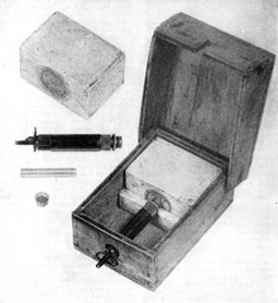
Figure 75.—Schü-Mine with Z.Z.42 Igniter.
e. WOODEN MINE 42(N).
(1) Description.
The body is made of impregnated wood, with a zinc socket in the top to take a detonator and igniter. Across the top is a shaped block of wood drilled to allow the igniter to be screwed down on the top of the body. The igniter is the standard D.Z.35. The main filling is cast TNT with pressed TNT primer.
(2) Characteristics.
• Length: 6 1/4 inches.
• Width: 6 1/4 inches.
• Over-all height: 5 1/8 inches.
• Height of body: 2 3/4 inches.
• Weight of filling: 3 pounds 5 ounces.
(3) Operation.
The mine is fired by pressure on top of the D.Z.35 igniter, or by pressure on a cover board over the head of the igniter. Without the cover board, the mine is practically insensible to blast, but the probability of operating the mine is reduced considerably. The functioning load of the igniter fitted to this mine is 75 pounds. It appears that the igniter is being manufactured with a weaker spring for use in this mine, since the pressure required to function a standard D.Z.35 is 130 to 165 pounds.

Figure 76.—Glass Mine 43 with (a) Hebelzünder Igniter, and (b) Buck Igniter.
f. ANTIPERSONNEL PRESSURE MINE (ITALIAN).
(1) Description.
This mine consists of a rectangular bakelite box, with a wedge-shaped, hinged lid, containing a TNT charge held in place by a projection and surrounded on the remaining three sides by deeply grooved fragmentation plates. The igniter mechanism consists of a metal tube which contains a spring-loaded striker, fitted with an actuating pin and a cocking ring. The outer end of the striker tube is secured against the wall of the box by a flange. The striker assembly slips into the side of the mine, in a recess cut out to receive it. A corresponding slot in the lid enables the mine to be completely closed when the igniter is not cocked.
(2) Characteristics.
• Length of box: 5.35 inches.
• Width of box: 2.56 inches.
• Depth of box: 1.5 inches.
• Length of charge: 26 inches.
• Width of charge: 1.97 inches.
• Depth of charge: 1.18 inches.
• Weight of charge: 5 1/4 ounces.
(3) Method of arming.
To arm the mine the igniter is cocked by pulling out the ring and inserting the actuating pin. The detonator is then inserted in the striker tube and secured by locking the ring. The whole assembly is inserted in the box, the detonator fitting into a recess in the explosive charge. Finally, the lid is gently closed until it rests on the actuating pin.
(4) Operation.
A slight pressure on the lid will cause it to push out the pin and release the striker.
(5) To Neutralise.
Avoid all pressure on the lid of the mine. Search for and neutralize any anti-handling devices. Lift the lid clear of the actuating pin. Insert a wire or nail in the safety-pin hole and lift out the striker assembly. Unscrew the locking ring and remove the detonator.
g. ANTIPERSONNEL GLASS MINE 43.
(1) Description.
This antipersonnel mine is made almost entirely of glass. It is armed with the chemical igniter or with the Hebelzünder. The bottom of the glass container is recessed to hold a Sprengkorper 28. On top of the mine rests a glass shear plate, and, on top of that, a thick glass pressure plate.
(2) Operation.
A pressure of 20 to 25 pounds breaks the thin shear plate and applies pressure on the lever of the Hebelzünder, thus firing the igniter and exploding the mine.
(3) To Neutralize.
If the mine is fitted with a Hebelzünder, remove the two glass plates, insert safety pin, and unscrew the igniter. Then remove the detonator. If it is fitted with a chemical igniter, unscrew the igniter by gripping it as low as possible. Do not grip the corrugated portion which crushes easily.
h. GERMAN ANTIPERSONNEL "POT MINE".
(1) Description.
A crush igniter is screwed into the top of the cylindrical body of this mine by means of an adapter. The pressed steel body contains an explosive filling of approximately 4 ounces of powdered picric acid.
(2) Operation.
A moderate pressure on the top of the igniter explodes the mine.
(3) To Neutralise.
Unscrew the igniter, grasping it as low as possible. If the detonator does not come out with the igniter, remove it by turning the mine upside down. If it does not then drop out, unscrew the adapter and remove the detonator. The total weight of the mine is 12 1/2 ounces.
i. MODIFIED Schü-Mine.
(1) Description.
This modified Schü-mine may be used with the Z.Z.35 igniter. The large lid has a sloping front through which the igniter plunger head protrudes.
(2) Operation.
Pressure on the lid causes the sloping front to push on the actuating pin. This pulls out the plunger of the igniter, causing it to fire. A hole is bored in the lid directly above the safety pin of the igniter. A cord attached to the ring of the safety pin is used to draw the pin out through the hole to arm the mine.
6. Antitank Mines
a. GENERAL.
The Germans use about 40 types of antitank mines, but the four types of Teller-mines are used most extensively.
b. TELLERMINE 43 (MUSHROOM).
(1) Description.
In place of the usual cover, this mine has a mushroom head pressure plate which screws into the igniter socket. Two threaded sockets are provided for subsidiary anti-lifting igniters, one in the side of the mine and the other in the base. The positions of these two sockets vary, although they always have been found on a diameter of the mine.
(2) Characteristics.
• Diameter over-all: 12.5 inches.
• Depth of body: 2.6 inches.
• Maximum height of mine: 3.5 inches.
• Diameter of mushroom head: 7.5 inches.
• Depth of mushroom head: 1 inch.
• Total weight of mine: 17 pounds 5 ounces.
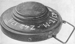
Figure 77.—Tellermine 43 (mushroom).
c. TELLERMINE 1942 (T.Mi.42)
(1) Description.
This mine consists of a cylindrical, pressed-steel body, containing a central detonator pocket which is surrounded by a priming cylinder of a composition resembling penthrite. Two pull igniter sockets are provided, one in the side of the mine 4 inches from the carrying handle, and the other in the base 2 inches from the center of the mine. These sockets are screwed into the body of the mine and waterproofed by rubber washers. A cylindrical cavity on the top of the mine contains the pressure-plate assembly. This pressure plate carries a rubber washer or aluminum strip, which is secured to it by a steel ring spot-welded to the plate and forming a seal where it passes under the lower edge of the flanged ring. A strong spring provides the resistance which must be overcome to depress the pressure plate. A central, threaded socket serves for the insertion of the igniter assembly, T.Mi.Z.42(15), consisting of a spring-loaded striker retained by a shear pin. The detonator resembles that used in the Teller-mine 35, but it screws into the body of the mine.
(2) Characteristics.
• Diameter of base: 12 3/4 inches.
• Diameter of base: 12 1/2 inches.
• Diameter of pressure plate: 5 3/4 inches.
• Maximum height: 4 inches.
• Type of filling: TNT.
• Weight of filling: 12 pounds.
• Weight of mine: 18 pounds (approximately)
(3) Functioning.
The mine functions when a minimum pressure of 495 pounds on the pressure plate causes the hexagonal cap to descend on the head of the plunger and shear the pin which retains the striker in the body of the igniter.

Figure 78.—Tellermine 42.
d. TELLERMINE 35 (STEEL) (T.Mi.35 Stahl).
This mine, 12 1/2 inches in diameter, weighs 21 pounds. Painted a matt gray, it is marked T.Mi.S 31 T Vii. 242 on the top in white paint; S88 12 42A, on the top in black paint; and WO 42, stamped on the top. In this model the pressure plate which extends over the entire mine is fluted, probably to prevent sand from blowing off when the mine is buried. In the center of the pressure plate is a threaded socket, closed by a screwed plug with a milled head. This socket will take the standard T.Mi. Z.35 igniter, but the mine can also be used with the igniter assembly of the Tellermine 42. The subsidiary igniter sockets are located on the bottom and side of the mine.

Figure 79.—Tellermine 35 (steel).
e. TELLERMINE 35 (T.Mi.35).
(1) Description.
This is a circular mine with a flat base and slightly convex cover. A strong spiral spring inside the mine holds the cover against the turned-in flange of a skirt screwed to the outside of the main body. The central hole for the main igniter (T.Mi.Z.35 or T.Mi.Z.42) is provided with a rubber washer to make a close joint with the body. When the T.Mi.Z.42 is used, a steel plug must be placed in the central well. Two holes for additional igniters are provided. The central tube, which takes the exploder system, contains the detonator, above which are two metal collars. Above these is a rubber ring, capable of compression to make the assembly watertight. The igniter screws into the cover of the mine, so that the lower face of the igniter presses hard against the rubber ring. One collar is a retaining collar for the detonator; the other is an adjusting or positioning collar for the igniter. The igniter is screwed into the correct position by a special tool, and when positioned it is secured by a small grub passing through the collar. If this collar has been removed, it cannot be replaced correctly unless the special tool is available. Incorrect positioning makes the mine either too sluggish or too sensitive.
(2) Characteristics.
• Diameter: 12.6 inches.
• Weight of mine: 19.2 pounds.
• Weight of filling: 11 pounds.
• Type of filling: TNT.
(3) Functioning.
The mine functions when the pressure on the cover compresses the mine spring, causing the body of the igniter to descend and shear the pin holding the striker. Pressure of 175 to 400 pounds will explode the mine.
(4) To neutralise.
Examine the sides and bottom of the mine for anti-handling igniters. Identify the igniters and neutralize. Remove the main igniter from the mine, manipulate the safety device, and immediately replace the igniter.

Figure 80.—Tellermine 35 with anti-lifting devices.

Figure 81.—Tellermine 35.
f. TELLERMINE 29 (T. Mi. 29).
(1) Description.
This mine was the first of the Tellermine series and was thought to have become obsolete, but it has been found in France since D-Day. It consists of a cylindrical body the lid of which is provided with three sockets for the reception of three Z.D.Z. 29 push-pull igniters. These igniters, according to a German document, are to be set at the heavy pressure setting (marked S or 125 kg.). Three additional sockets, two in the side and one in the base provide means of attaching anti-handling igniters.
(2) Characteristics.
Diameter: 10 inches.
Height: 2.7 inches.
Weight: 13.2 pounds.
Weight of filling: 10 pounds.
Type of filling: TNT.
Firing pressure: 100-275 pounds.
(3) Neutralisation.
Search for and neutralize anti-handling devices. Unscrew the three igniters. The mine is now safe.

Figure 82—Tellermine 29.
g. L. Pz. ANTITANK MINE.
(1) Description.
This is a circular mine with flat top and bottom, enclosed in two saucer-shaped covers. In the center of the top is a small cover plate secured by bayonet catches under which is a safety screw which when screwed tightly clockwise closes the entry to the detonator. Above the blasting cap is a small chamber from which fire tubes lead radially to the five special pressure igniters action of which is similar to that of the D.Z. 35 pressure igniter.
(2) Characteristics.
• Diameter of mine: 1 foot.
• Height: 3 inches.
• Weight of mine: 8 pounds.
• Weight of filling: 5 pounds.
• Nature of filling: TNT.
(3) Functioning.
Pressure on the lid causes one or more of the igniters to fire, setting off the mine.
(4) Neutralization.
Search for and neutralize any anti-handling devices. Remove cap and screw safety screw clockwise until line marked SICHER coincides with white mark on case. If all the nuts on the bottom of the mine are present and screwed up, mine is safe.

Figure 83.—L. Pz. Mine.
h. Topf MINE.
(1) Description.
The mine body is a hollow cylindrical disc of plastic material filled with HE. Its top face is formed as a circular pressure plate surrounded by a shear groove. The cylindrical recess in the center of the mine body accommodates the primer plug. The carrying handle is fixed to the mine bottom by two glass screws.
The primer plug assembly consists of a glass screw cap and the cylindrical igniter seating, made of bituminous cardboard material.
(2) Action.
Under a load of 330 pounds, the pressure plate shears along its shear groove and comes to rest on the pressure head of igniter, crushing it and causing the mine to explode.
(3) To neutralize:
(a) Search for and neutralize any anti-handling devices.
(b) Ensure that the mine is undamaged.
(c) Lift carefully, rest on one side, and unscrew the primer plug.
(d) Remove the igniter.
(e) Unscrew protective detonator pocket.
(f) Remove the detonator and replace the protective pocket on the igniter.

Figure 84.—Topf Mine.
i. Riegel. ANTITANK MINE (R. Mi. 43).
(1) Description.
The mine consists of an encased explosive charge and of an outer box in two parts, lid and tray. The charge is provided with five standard igniter sockets, one on top, two on one side, and one at each end. Holes in the box correspond with the sockets on top and on the side, enabling igniters to be inserted from outside and fitted as anti-handling devices.
Z.Z.42 igniters are inserted in the end sockets and their pins rest on shoulders at each end of the tray and are covered by swivel clips. The charge is supported in the tray by two shear wires. For transport, two safety bars are inserted which take the weight of the charge off the shear wires. When the safety bars are withdrawn, spring-loaded shutters close the holes. These shutters can be opened by pushing a pencil or large nail through a hole in the base of the tray.
The lid rests on the charge, and the ends of the shear wires are led up over the lid and windlassed together to keep it on.
(2) Characteristics.
• Length: 31.5 inches.
• Width: 3 3/4 inches.
• Height: 3 1/2 inches.
• Weight of mine: 20.5 pounds.
• Weight of explosive: 8.8 pounds.
• Nature of explosive: Amatol 50/50.
(3) Functioning.
Pressure on the lid of the mine shears the shear wires and the pins of the Z.Z.42 igniters are pushed out, thus setting off the mine.
(4) Neutralization.
Search for and neutralize any anti-handling devices. Turn the mine on its side and by pushing a pencil or nail through the hole in the base raise the shutters covering the safety bar holes. Insert safety bars. Cut shear wires and remove lid. Open swivel clips and, having seen that the pins of the Z.Z.42 igniters are resting on the shoulders and not beneath, take out the charge case. Unscrew the Z.Z.42 igniters.
NOTE: The charge case can be inserted with one Z.Z.42 igniter pin reversed and beneath the shoulders. In this case the charge case must be slid out by lifting the end in which the Z.Z.42 igniter is used normally.

Figure 85—Riegelmine 43 (R. Mi. 43).
j. FRENCH LIGHT ANTITANK MINE.
(1) Description.
The mine body consists of a rectangular steel body filled with 5 3/4 pounds of HE. In the top of the mine are two igniter pockets, one at either end. The body is covered with a slip-on rectangular cover the top of which is corrugated. There is a square hole in either end of the cover through which passes a safety bar which is removed when the mine is laid.
(2) Action.
A pressure of from 300 pounds to 500 pounds in the lid causes it to descend on the igniters, exploding the mine.
(3) Characteristics.
• Length: 9 1/2 inches.
• Width: 5 1/2 inches.
• Height: 4 1/2 inches.
• Weight: 14 1/2 pounds.
(4) To neutralise:
(a) Search for and neutralize any anti-handling devices.
(b) Lift cover and remove both igniters.
(c) Replace the cover.
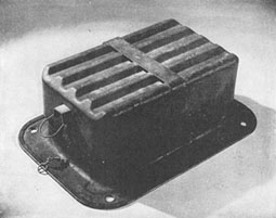
Figure 86.—French light antitank mine.
k. WOODEN-BOX MINE 42 (Holzmine).
(1) Description.
The body of the mine is a rectangular wooden box containing 11 1/2 pounds of HE. A pressure block protrudes through the lid of the mine, which inside the mine rests on a shear flange secured to the side of the mine by wooden dowels.
The mine is gray or unpainted, with a red band on one side and on the face of the pressure block.
(2) Action.
Pressure of 200 pounds or more on the pressure block shears the dowels securing the shear flange, which when forced down pushes out the pin in the Z.Z.42 igniter, exploding the mine.
(3) Characteristics.
• Length: 13 inches.
• Width: 12 inches.
• Height: 4 1/2 inches.
• Weight: 18 pounds.
(4) Neutralising.
Search for and neutralize any anti-handling devices. Remove the lid avoiding all pressure on the pressure block. Lift pressure block clear of the shear flange. Place the pressure block so it bears on the supporting block in the unarmed position. Replace the lid.

Figure 87.—Wooden Box Mine 42.
ANTITANK MINES IN USE BY THE GERMANS

Figure 88.
7. Igniters
a. PULL IGNITERS.
(1) Bakelite Z.Z.42 (Zugzünder 42).
The pin, the striker, and the actuating spring of this igniter are steel. The body and the collar are plastic mouldings, and the cap holder is brass. Between the lower end of the spring and the striker head are a metal washer and a felt washer which act as a guiding gland. The over-all length is 37/16 inches, and the diameter is1/2 inch.
(2) Zugzünder 35 (Z.Z.35).
(a) Description. This igniter is used with trip wires to operate S-mines, improvised mines, and booby traps. The heavy antitank mines have this igniter as a booby trap against lifting the lid, and it also is used as an extra igniter in Tellermines and as the main igniter in the drifting mine. The brass body of the igniter contains a sliding cylinder, a compressing spring, the striker, and the striker spring. In the unarmed position, the safety pin is prevented from falling out by a nut on the end of the pin and by a spring clip. When the nut is removed prior to arming, the clip still holds the pin in place until it is pulled away by a cord.
(b) Operation. In the armed position the striker is held only by two small cotters, which project into the groove behind the head of the striker. When the sliding cylinder is pulled up about 3/16 inch, the cotters are freed and move outwards, releasing the striker. The pull required to fire the igniter is 9 to 13 pounds.
(c) To neutralize. The igniter is made safe by pushing a small nail through the hole in the striker. The trip wire then may be cut.
(d) To disarm. When the igniter is fitted into a mine or charge, unscrew the igniter with the nail in place and remove the detonator.
(3) Zug-und Zerschneidezünder 35 (Zu. Z.Z.35).
(a) Description. This igniter is used chiefly in places where tension wires are easily concealed. It functions in two ways—either by pull on a wire or by cutting the wire. In both cases it is set by securely fastening a wire through the hole in the head of the movable cylinder. The body of the igniter contains a movable cylinder, a striker spring, and the striker. The striker is held in position by two cotters. The movable cylinder slides inside a sleeve fitted in the end of the main housing. This sleeve has two slots through which the safety pin passes. These slots allow for adjustment of the igniter when setting the charge. When the igniter is to be armed, the wire is attached to the cylinder and given enough tension to hold the safety pin near the center of the slot. This ensures easy withdrawal of the safety pin after the charge or mine has been laid. Before withdrawal of the pin the nut is removed from the end of it.
(b) Operation. When properly armed the igniter will function if the tension wire is pulled or cut.
(c) To neutralize. If the safety pin has been removed, and the tension wire is intact, push a small nail through the safety-pin hole, and, after determining that there is no igniter on the other end of the wire, the wire may be cut.
b. PRESSURE IGNITERS.
(1) Drücksünder 35 (DZ.35 Type A).
(a) Description. This is a mechanically-acting, push igniter, designed for use with improvised mines and booby traps. It is also the main igniter of the heavy antitank mine. It consists of an aluminum body and a plunger which carries the 1 1/4-inch pressure head. The plunger is held away from the cap by a strong spring. Within the plunger is a recess for the striker and spring. Two steel balls rest partly in two holes in the plunger and retain the striker in the cocked position. When in the safe position, the plunger is prevented from moving by a safety pin.
(b) Operation. After withdrawal of the safety pin the igniter is fired by pressure on the head, which depresses the plunger until the steel balls are free to escape into the space in the guide. The striker then is released and fires the cap. A pressure of 130 to 160 pounds (corresponding to a depression of about 1/3 inch) is sufficient to fire the igniter.
(c) To neutralise. Push a nail into the safety pin hole and secure it in place to prevent its falling out.
(d) To disarm. After neutralizing the igniter, unscrew it from the charge and remove the detonator.
(2) Drückzünder 35 (DZ.35 Type B).
(a) Description. This igniter functions exactly the same way as type A, though its construction differs in a few minor details. The body is made of unpainted brass, and the diameter of the pressure head is 1 inch. The retaining steel balls are replaced by two small cotters, placed below the head of the striker. The cap is located in the base plug.
(b) Operation. After withdrawal of the safety pin, the igniter is fired by pressure on the head. When the plunger is depressed about 1/3 inch, the two small cotters escape from the guide into the space below. The striker then is released and fires the cap. The pressure required in some cases is as low as 50 pounds.
(c) To neutralize. Same as for Type A.
(d) To disarm. Same as for Type A.
(3) S-Minenzünder 35 (S.Mi.Z.35).
(a) Description. This igniter is used to initiate the S-mine when set as a pressure operated charge. The body of the igniter is made of aluminum and holds a pressure spring, plunger, striker, and striker spring. A central part of the body acts as a distance piece and guide for the plunger. Three steel antennae, 1 1/4 inches long, are screwed to the head of the plunger. This hollow plunger takes the striker, which is held in position against its spring by two steel balls. The balls are held partly in two holes in the plunger and partly in a groove in the striker. The safety pin is retained in its hole by a spring-loaded and milled nut. When the safety pin is withdrawn, the mine is armed.
(b) Operation. Pressure on the antennae causes the plunger to descend, and after moving approximately 0.2 inch the steel balls fall away releasing the striker. The firing pressure is approximately 15 pounds.
(c) To neutralize. Push a nail into the safety pin hole. Care must be taken in handling this igniter as a slight steady pressure may cause it to function.
(4) Tellerminenzünder 42 (T.Mi.Z.42).
This igniter consists of a simple steel striker retained against the pressure of a steel spring by a shear wire. The striker is in a steel casing. A percussion cap is at the base of the casing. The pressure necessary on the head of the striker is approximately 400 pounds.
(5) Tellerminenzünder 43 (T.Mi.Z.43).
(a) Description. The chief feature of this igniter, which can be used in Tellermines 35, 35 (steel), 42, and 43, is that once it has been placed in the mine and armed it cannot be removed without exploding the mine. The head of the T.Mi.Z.43 is approximately 1/4 inch higher than that of the T.Mi.Z.42. The upper shear pin is 1/4 inch above the body of the igniter. The outer ends of the arming shear pins can be seen on the sides of the igniter body, either 1/2 inch or 7/8 inch below the top of the igniter body. The igniter consists of a body into which is pressed a cap retainer. Inside is a pressure sleeve, which protrudes above the casing. The upper part of the sleeve is fitted with a strong shear pin, and the lower part is connected to the igniter body by a weak brass arming wire. Inside the pressure sleeve is a plain tubular striker guide containing the striker, held in place by two retaining balls.
(b) Operation. The igniter is inserted in the normal manner, and the top of the mine is screwed on. This depresses the pressure sleeve, which in turn shears the weak arming pins with an audible snap. The anti-lifting device of the igniter now is armed. The igniter can be set off in either of two ways. When the pressure plate is crushed or depressed, the sleeve is pressed down until the strong shear pin is cut. The retaining balls escape into the recess above the shoulder of the sleeve, freeing the spring-loaded striker which fires the percussion cap. Any attempt to unscrew the pressure plate or cap of the mine will cause it to explode. Under pressure of the spring the sleeve follows any upward movement of the plate or cap and after about 1/8 inch upward travel the balls escape below the sleeve, again releasing the striker.
(c) Disarming. Since there is no way to determine whether a Tellermine is armed with this igniter, no pressure plate or screw caps should be removed from these mines. They should be lifted and destroyed. However, should it be necessary to determine the type of igniter, wind a rope or tracing tape counter-clockwise around the pressure plate or screw cap four complete times. Then pull from a safe distance to unscrew the plate or cap.
(6) T.Mi.Z.35.
(a) Description. This pressure igniter has only been found in Tellermines. The brass body contains a floating striker assembly. The striker head is stepped to fit a projection on the spindle. This is a secondary safety device to keep the weight of the striker off the shear pin until the igniter is armed. A white mark with the word Sicher (safe) above it, and a red mark with the word Scharf (armed) above it are inscribed on the head of the igniter. When the screw head is turned so the red spot moves from the safe to the armed position, the projection moves clear of the striker head.
(b) Operation. In the mine the lower face of the guide compresses the ring situated above the adjusting collar. Pressure on the cover of the mine moves the body of the igniter down against the rubber on the collar and so exerts a force on top of the striker, shearing the pin. The striker then moves under the pressure of the spring.
(c) To neutralize. If the mines have been subjected to blast, unscrew the igniter gently. Hold the igniter clear of the mine with the cap pointing away. Turn the red spot on the screw head from Scharf to Sicher. Fix the claw attached to the wire, or a similar improvisation, into the slotted end of the safety bolt, and press the safety bolt home. Replace the igniter in the mine, screwing it in hand tight. If the mines are known to be in good condition, turn the red spot from Scharf to Sicher, using a coin, not a screwdriver. Fix the claw attached to the wire into the slotted end of the safety bolt and press the bolt home.

Figure 89.—Friction Igniters.

Figure 90.—Pull Igniters.

Figure 91.—Pressure Igniters.
c. OTHER IGNITERS.
(1) Pressure Release Device, E.Z.44 (Entlastungzünder 44).
(a) Description. This device is intended primarily for booby-trapping Tellermines. Any attempt to remove the mine permits a plunger to rise, setting off an 8-ounce charge of TNT-PETN. A weight of 10 pounds is sufficient to hold the device in the armed position, and a built-in clockwork, time-delay protects the person setting it from premature detonation. The device is housed in a steel body crimped at the base. The operating mechanism fills one-half of the container, while the explosive occupies the remaining space. The operating mechanism includes the pressure release assembly, including plunger, plunger spring, and striker retaining arm; the clockwork mechanism; and the firing assembly, including striker, striker spring, percussion cap, detonator holder, and detonator.
(b) Operation. The clockwork mechanism is wound. A weight of at least 10 pounds is placed on the plunger. The safety bar is released, permitting the clockwork mechanism to function for 1 1/2 minutes with a loud buzzing sound, withdrawing the internal safety pin. The device now is armed.
(c) To neutralize. Once this device is armed it cannot be neutralized.

Figure 92.—Pressure Release Device E.Z. 44.
(2) Tilt Igniter, Ki.Z.43 (Kippzünder 43).
(a) Description. The tilt igniter is designed to fire whenever the tilt rod is moved in any direction. This tilt rod is on top of the igniter, which contains a sliding pressure piece, pressure spring, hollow striker, striker spring, and two retaining balls. The detonator assembly includes percussion cap and detonator. An extension rod, 24 3/4 inches long, is connected by pushing the sleeve over the tilt rod.
(b) Operation. The igniter is armed by removing the safety pin. When the tilt rod is moved in any direction, the tilt-rod base is tilted inside the igniter body, depressing the pressure piece, thus freeing the striker. A lateral pressure of 15 to 23 pounds on the end of the tilt bar will fire the igniter. Use of the extension rod reduces the pressure needed to explode the igniter to 1 1/2 pounds.
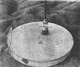
Figure 93.—Tellermine with Tilt Igniter attached.
(3) S-Mine Igniter 44.
(a) Description. This igniter is a combination push-and-pull type, with the standard German igniter thread. It can be used in mines and charges other than the S.Mi.44. The steel case of the igniter contains a spring-loaded striker above a percussion cap and detonator socket. The striker protrudes through the top of the igniter. Two flat, winged, actuating pieces are held together at the top by a safety pin. Holes in these pieces serve for the attachment of trip wires.
(b) Operation. The igniter is armed after the safety pin is withdrawn. A pressure of 21 pounds on the wings of the actuating pieces, or an outward pull of 14 pounds on the trip wires, opens the winged actuating pieces sufficiently to release the striker and fire the percussion cap.
(c) To neutralize. This igniter requires extreme care in neutralization. In place the igniter is completely covered, leaving only the wings exposed. Carefully locate the wings and remove enough earth to insert a safety pin or nail through the pin holes. If trouble is encountered in inserting the pin or nail, the mine is dangerous and should be destroyed in place. Unscrew the igniter, lift the mine, and remove the detonator.

Figure 94.—Clockwork Long-delay Igniter (J-Feder 504).
(4) Clockwork long delay igniter (J-Feder 504).
This igniter is a clockwork mechanism that may be set to function at any desired delay from 10 minutes to 21 days. It is used for special demolitions.
(5) Crush Type Chemical "Buck" Igniter.
(a) Description. This igniter is a chemical, crush-actuated type, consisting of a thin metal drum, with circumferential grooves to reduce its resistance to vertical pressure. It contains a glass ampule half filled with acid, surrounded by a white, powdered, flash composition. It weighs 1 ounce.
(b) Operation. A moderate pressure on top of the igniter crushes the metal drum and the glass ampule inside it. The acid pours into the white powder, and a flash results, setting off detonator and mine.
8. Bridging Equipment
a. GENERAL.
(1) Development.
Apart from the introduction of a 60-ton type in the armored division bridging column, German bridging equipment has undergone few important changes since the beginning of the war. Standard types are not numerous; particular emphasis is placed upon the construction of improvised bridges at the earliest possible stage of a river crossing.
(2) Bridging Operations.
The initial stage of an assault crossing is carried out by storm boats. These may be supplemented by pneumatic boats supplied in three sizes. Once a bridgehead has been established, pneumatic boats play an important part, either in ferrying personnel and stores, or in construction of rafts and light bridges. The superstructure for these light bridges consists of standard timber members carried ready for construction. Ready made timber bridges for crossing dry gaps also are carried, and some engineer units carry a light box girder and pontoon equipment known as bridging equipment "D". In the third stage of a river crossing, when the bridge is required for normal traffic of approximately 24 tons, bridges from the divisional bridging column are used. Of these, there are two types: bridging equipment "B", a pontoon trestle bridge; and bridging equipment "K", a box girder bridge supported on pontoons and trestles. A third type, bridging equipment "J", designed to accommodate the heavier German tanks, replaces the "K" equipment in armored divisions.
b
Heavier semi-permanent bridges includes the L.Z. bridge, a Sectionalized, through-girder type which is launched from a roller bed; the Herbert, with a girder superstructure supported on large Sectionalized pontoons, and the "S" equipment, used for heavy traffic over wide rivers and consisting of a double-way superstructure on Sectionalized pontoons similar to those of the Herbert. Railway bridges are represented by the Roth-Wagner, Krupp, and Ungaw bridges.
b. BOATS USED IN RAFTING AND BRIDGING.
(1) Small pneumatic boat.
• Length: 9 feet 10 inches.
• Beam over-all: 3 feet 9 inches.
• Weight: 116 pounds.
• Capacity: 3 armed men or 660 pounds.
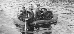
Figure 95.—Small pneumatic boat
(2) Pneumatic boat assault bridge.
This bridge can be built in any lengths in a current up to 2 1/4 knots and will carry infantry in single file.
• Weight of superstructure—12.8 pounds per foot.
• Total weight of bridge—23.7 pounds per foot.
(3) Medium pneumatic boat.
(a) Description. These pneumatic boats can be used as supports for the standard German 2 1/4-ton, 4 1/2-ton, and 9-ton rafts. The 2 1/4-ton raft consists of two boats; the 4 1/2-ton raft has four boats in the form of two pairs in tandem, and the 9-ton raft has three pairs in tandem.
(b) Characteristics.
• Length over-all: 18 feet.
• Beam over-all: 6 feet 1 inch.
• Weight: 330 pounds.
• Crew: 7 men.
• Capacity, not including crew: 1.35 tons.
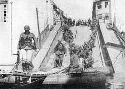
Figure 96.—Track bridge and medium pneumatic boat.
(4) Motor boat.
(a) Description. This craft is used primarily for pushing and towing rafts and bridge sections in bridging operations. It also can be used for river reconnaissance and barge towing. It is transported on a special two-wheel trailer, which is provided with gear so the boat can be launched and recovered direct from the trailer. The motor boat is a broad-beamed craft constructed of steel plates with copper-nickel rivets.
(b) Characteristics.
• Length over-all: 23 feet.
• Beam over-all: 6 feet 7 inches.
• Depth amidships: 4 feet.
• Draught, fully laden: 2 feet (approximately).
• Weight of boat unloaded: 2 tons (approximately).
• Capacity, when not towing: 6 men, including crew, or 1.7 tons evenly distributed on floor boards.
• Speed, towing tension 1.4 tons: 5 1/2 knots.
• Speed, towing tension 1,900 pounds: 7 knots.
• Capacity of fuel tank: 33 gallons.
• Maximum running time on full tank: 6 hours (approximately.
(c) Engine. The boat is driven by a six-cylinder, Maybach-type, S5, water-cooled, gasoline engine.
• Horsepower: 80 at 1,400 rpm.
• Total engine capacity: 7 liters (427 cubic inches) (approximately)
• Maximum permissible revolutions in still water: 1,400 rpm.
(d) Trailer. The two-wheel trailer includes chassis, extensible tipping slipway, traveling cradles, winch, and hoisting cable. It has the following characteristics:
• Weight, unloaded: 2 1/4 tons.
• Length over-all: 24 feet 9 inches.
• Length with boat: 28 feet 6 inches.
• Length extended: 32 feet 4 inches.
• Width over-all: 6 feet 7 inches.
• Length of hoisting cable: 49 feet 3 inches.
• Working party: 6 men.
(5) Storm boat.
(a) Description. This boat, when in operation, is carried and launched by eight men, while four men are required to carry and install the motor. The boat is steered by pivoting the motor on the bracket which attaches it to the stern. The helmsman stands in the stern gripping two handles at the front of the motor.
(b) Characteristics.
• Length: 19 feet 9 inches.
• Beam: 5 feet 2 inches.
• Depth amidships: 2 feet 1 inch.
• Weight: 475 pounds.
• Material: Wood.
• Crew: 2 men.
• Capacity: 7 men in addition to crew.
• Maximum speed, loaded.: 15 to 16 knots.
• Transport: 3 boats with motors on special trailer.
(c) Engine. This is a "mechanical oar" propulsion unit: a propeller attached to a long shaft running through a casing bolted to the engine. The propeller revolves several feet behind the boat.
• Length: 13 feet 6 inches.
• Width: 2 feet 9 inches.
• Height: 2 feet.
• Weight (without oil and fuel): 375 pounds.
• Weight (with oil and fuel): 412 pounds.
• BHP: 30.
• Cylinders: 4, horizontally opposed.
• Running time on full tank: 1 1/2 hours.
• Propeller: 3 blade, 10 3/4 inches in diameter.
(6) Large pneumatic boat.
This is the largest of the three standard pneumatic boats and is generally used singly.
• Length over-all: 26 feet.
• Beam over-all: 9 feet 9 inches.
• Weight: 637 pounds.
• Maximum buoyancy: 13.5 tons.
c. PONTOON AND TRESTLE BRIDGES.
(1) Training pontoon bridge.
(a) Description. There is little evidence of this equipment being used operationally; it is thought to be kept for training. There are two types of light pontoon and trestle bridges: one with half pontoons having a load capacity of 4 tons, and the other with double-pontoon piers having a load capacity of 5 1/2tons. The decking used for this bridge also is used in bridging and rafting with pneumatic boats.
(b) Characteristics.
• Half pontoon:
• Length: 12 feet.
• Beam: 5 feet.
• Depth: 2 feet 6 inches.
Superstructure:
Timber with decking: 20 feet by 2 feet.
Track width: 8 feet.
Bay length: 20 feet.
(2) Pontoon and trestle bridge (Czech).
This equipment consists of steel half pontoons and center sections. Two types of bridges are built.
(a) Roadways built on piers of one half pontoon and one center section, with a capacity of 8.2 tons and the following characteristics.
Pier length:
• Half pontoon: 16 feet.
• Center section: 8 feet.
• Beam: 4 feet 6 inches.
• Track width: 8 feet.
• Bay length: 21 feet.
(b) Roadway built on piers of two half pontoons and one center section, with a capacity 16.5 tons and the following characteristics:
• Track width: 8 feet.
• Bay length: 21 feet.
• Complete pier:
• Width: 4 feet 6 inches.
• Length: 40 feet.
(3) Light pontoon and trestle equipment (Brückengerät C).
The three following types of bridges can be built with this equipment.

(4) Medium pontoon and trestle equipment (Brückengerät T).

(5) Heavy pontoon and trestle equipment (Brückengerät B).
This is the standard combat equipment of the German Army.
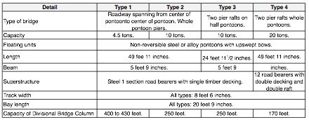
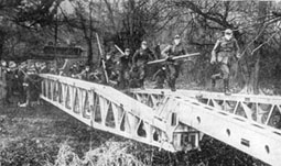
Figure 97.—K Bridge.

Figure 98.—L.Z. Bridge.
(6) Light timber bridges on fixed supports.
(a) Folding single span foot bridges. This equipment is made up of two single members, hinged together, and consisting each of two 3-inch round timber roadbearers supporting three cross bearers to which are wired two planks (9 foot 10 inches by 10 inches by 3 1/2 inches. This bridge is trussed by means of a timber strut a short distance off center and a system of ties. The total length of the bridge is 19 feet 8 inches.
(b) Light tracked bridge.
This is a light tracked timber bridge, constructed in two load ratings: 6 tons and 9.5 tons. It generally is supported by simple framed trestles, but if floating supports are needed the large pneumatic boat is used. The following tables give the cross sections of the roadbearers for varying spans and loads:

(7) 27-Ton heavy tracked bridge.
(a) Description. This bridge is a variation of the light tracked bridge, with a capacity of 27 tons, it consists of two bays and a span of 29 feet 6 inches. A single bent framed trestle is used as a central support.
(b) Components.
Bridge seats:
• Length: 13 feet.
• Width: 11 inches.
• Depth: 8 inches.
Ramps:
• Length: 5 feet.
• Width: 4 feet 9 inches.
Roadbearers:
• Length: 14 feet 9 inches.
• Width: 7 inches.
• Depth: 9 1/2inches.
Track section:
• Length: 4 feet 11 inches.
• Width over-all: 4 feet 9 inches.
• Useful width: 4 feet 3 inches.
Trestle - Capsill and Groundsill:
• Length: 13 feet.
• Width: 7 inches.
• Depth: 8 1/2inches.
d. FIXED BRIDGES.
(1) Small box girder (Brückengerät K).
This equipment is capable of carrying heavy vehicles and light tanks over short gaps. It is essentially an assault bridge and can span gaps of 31 feet 6 inches, 47 feet 3 inches, or 63 feet with box girders alone. The bridge always is built with three girders and has a carrying capacity of 27 tons. Trestles and pontoons are supplied to span wet or dry gaps with a series of bridges.
(2) Light sectional bridge (Leichte Z Brücke).
This is a through bridge with a timber roadway, approximately 12 feet wide, slung between two main girders of braced steel panels 8 feet 2 inches long and 7 feet 10 inches high. The normal bridge cannot span a gap greater than 147 feet 6 inches, and is rated over this and all lesser spans at 33 tons for tanks. With special underslung bracing the span may be increased to 172 feet without altering its rating.
(3) Herbert Bridge.
This bridge is sometimes called the "Italian Meccano Bridge". It is through-girder type with a 10-foot clear roadway. Each girder is constructed of steel lattice pyramids, made of angle iron and channel struts. The decking is of 6-inch timber plank. The German classification of this bridge is 18 tons over 82 feet. This bridge also may be used in conjunction with trestles or pontoons.
e. Heavy Bridging Equipment. J 42 and J 43 Bridging Equipment (Brückengerät J 42 and J 43). The J 42 equipment consists of steel box-girder sections, of which any number up to four can be bolted together to form a maximum span of 64 feet. Each section is about 16 feet 6 inches long. A decking of stout chesses is laid on these main bearers and held down by two similar box girders used as vibrants. The girders are launched over rollers. Trestles and four-section pontoons are used as supports. The single track width of the bridge is believed to be 13 feet 9 inches, but it also can be constructed in double track width. The J 43 bridge is a strengthened version of the J 42.

Figure 99.—Herbert Bridge.
9. Mechanical Equipment
a. 6-TON MOBILE CRANE (Sd. Kfz. 9/1) (Drehkran Kraftwagen 6 t.).
This crane is mounted on the chassis of the 18-ton semi-tracked vehicle (Sd. Kfz. 9). It has a telescopic jib mounted on a ball-bearing base, which permits a traverse of 180 degrees and an adjustment for ground slope up to 12 degrees in any direction. The jib has two radii of operation according to the lifting capacity: 6 tons for the smaller radius and 4 tons for the larger radius.
b. WIRE CUTTERS.
(1) Large type.
These cutters are approximately 2 feet in length and weigh 5 pounds. The two jaws of special steel are pivoted on two links and operated by a pair of tubular steel handles. These are hinged together and covered with insulated grips which are secured by terminal caps and locking rings. A short pin acts as a stop.
(2) Small type.
These cutters are 1 foot 4 inches long and weigh 2 3/4 pounds. There are minor variations in construction among samples manufactured by different firms. The general design is similar to that of the large cutters, but the shape of the jaws is different, one jaw being bent over in the form of a hook to aid in holding the wire. The handles have insulated grips.

Figure 100.—Wirecutters.
c. BLAST DRIVE ROD.
This equipment is designed for the rapid production of small diameter vertical holes in the ground for telegraph poles or similar supports. The equipment includes a drive rod; two tabular hand levers; a long, thin, metal rod; and a propellent charge, safety fuze, and igniter.
d. GERMAN PORTABLE POWER SAWS.
(1) Light power saw.
(a) Description. The main components are the gasoline motor with its gearing, the clutch, saw blade, and saw chain. The saw blade can be turned through 90 degrees for horizontal or vertical cutting and is locked in position by a lever.
(b) Characteristics.
• Weight including fuel: 111 pounds.
• Effective length of blade: 3 feet 3 inches.
• Revolutions per minute: 2,600.
• Speed of cutting chain: 21 feet per second.
• Fuel consumption: 1 3/4 to 2 1/2 pints per hour.
(2) Heavy power saw.
(a) Description. This is similar to the light power saw. It is too heavy for hand use and is provided with three adjustable legs and a large bogie for wheeling into position. The saw blade can be swivelled about the axis of the chain drive wheel, as well as vertically of horizontally.
(b) Characteristics.
• Weight including fuel: 172 pounds.
• Effective length of blade: 3 feet 3 inches.
• Revolutions per minute: 2,300.
• Speed of cutting chain: 23 feet per second.
• Fuel consumption: 2 1/2to 3 pints per hour.

Figure 101.—Electric chain-saw.
e. ELECTRIC GENERATORS AND ELECTRIC POWER TOOLS.
(1) Field generating set
(a) Description. This field generating set is used by German army engineers in mobile workshops for power driven tools. It is also used for charging storage batteries.
(b) Characteristics.
• Designation: Maschinensatz 220/380.
• Weight: 507 pounds.
• Motor: 2 cylinder, 2 stroke.
• Type of generator: AC.
• Kilowatts: 6.
• Volts: 220/330.
(2) German electric two-speed drill.
This machine is used for boring holes in the construction of improvised bridges. The drill normally uses its own detachable mounting but, for boring wood, it may be held by hand. The drill consists of a 50-cycle AC motor, consuming 800 watts, fitted with a Morse taper sleeve and a two-speed gear box giving 200 to 400 revolutions per minute.
f. GERMAN PILE DRIVERS.
(1) Field Pile-Driving Frame 1939.
(a) Description. This equipment consists of a guide mast with a double block at the top, supported on a base by two back stays. For pile-driving from land the frame is mounted on four wheels. These wheels are replaced by beams when pile-driving is carried on from a raft. A two-drum, hand winch serves to raise and lower the pile driver. The following can be operated on the frame:
(b) Characteristics.
• Three-piece hand-operated monkey: 440 foot pounds.
• Compressed air pile driver: 360 foot pounds.
• Compressed air pile driver: 1,440 foot pounds.
• Diesel pile driver: 992 foot pounds.
• Diesel pile driver: 1,323 foot pounds.
(2) Pneumatic pile driver (360 foot pounds).
(a) Description. The main components are a stationary part, consisting of the piston, piston rod, and piston base; a moving part (monkey) consisting of driving block, cylinder, and screw-in cylinder head; a spring-loaded clamping device, and a guide for use with the pile-driving frame 39. The driver is the fast hitting type and attains its high rate because the acceleration of the moving portion is due not only to its own weight but also to the compressed air operating downwards on an internal flange at the base of the bore of the cylinders.
(b) Characteristics.
• Weight of monkey: 121 pounds.
• Cylinder: 2.5 inches.
• Stroke: 1 foot 5 3/8 inches.
• Force per blow: 360 foot pounds.
• Striking rate: 105 per minute
(3) Pneumatic pile driver (1,440 foot pounds).
(a) Description. This pile driver is similar to the lighter one, but it has a heavier monkey and a longer stroke. This driver is the free falling type. The monkey is lifted up by compressed air, falls freely onto the base plate, and gives up its kinetic energy to the. pile after covering a stroke of little more than a yard.
(b) Characteristics.
• Weight of monkey: 448 pounds.
• Cylinder base: 3 9/16 inches.
• Stroke: 3 feet 3 1/2 inches.
• Force per blow: 1,440 foot pounds.
• Striking rate: 54 per minute.
(4) Diesel pile driver (992 foot pounds).
(a) Description. The main components are the piston with anvil, the monkey, the guide tubes, the headpiece, and the fuel tank. This diesel pile driver works on the two-stroke principle: an explosion takes place on each hitting stroke. The required ignition temperature is reached through the compression of the air trapped between the top of the falling piston and the monkey.
(b) Characteristics.
• Weight of monkey: 980 pounds.
• Total weight: 2,100 pounds.
• Stroke: 4 feet 7 inches.
• Striking rate: 56 per minute.
(5) Heavy diesel pile driver.
(a) Characteristics.
• Weight of monkey: 1,100 pounds.
• Cylinder base: 8 1/4 inches.
• Stroke: 7 feet 2 5/8 inches.
• Energy per blow: 8,255 foot pounds.
• Striking rate: 50 per minute.
g. WATER SUPPLY AND WATER PURIFICATION.
(1) Portable haversack filter.
This filter, issued on a company basis, is a standard item of equipment in the German Army. Performance is said to be from 22 to 55 gallons of water per hour, according to the amount of solid matter in suspension. Although the action of the filter is purely one of clarification, it is claimed by the Germans that it effectively will treat "naturally" contaminated water, that is water in which corpses have been lying. However, it will not rid the water of objectionable smell, nor is it effective against water containing chemical agents or substances in solution.

Figure 102.—Haversack water filter.
(2) German Tube Well 1937 Pattern, with Accessories "A" and "B".
This tube well is a suction pump capable of lifting water from a depth of 26 feet. Accessory "A" extends the depth to about 33 feet. Accessory "B" permits the pump to be used for pumping surface water.

Figure 103.—Tube well set with accessories.
h. MARKINGS OF CYLINDERS OF INDUSTRIAL GASES.
The Germans always stamp the type of gas their cylinders contain into the metal itself as guide in case the paint should change color or disappear through weathering.

i. EARTH MOVING EQUIPMENT.
Trench plows. Small and large trench plows are used by the German Army. The small trench plow consists of a double plowshare on the hooked end of a girder which is supported on a two-wheeled trailer and towed behind a semi-tracked vehicle. The large plow consists of the plow, anchor, pulley assembly, tow wire, and support.
j. AIR COMPRESSORS AND PNEUMATIC TOOLS.
(1) Sinker rock drills.
There are two types of sinker rock drills used by the German Army: the "D" handle and the "T" handle types. Both, judged by American standards, fall into the lightweight class (40 to 50 pounds). These tools are similar in design but the internal parts are not interchangeable. Both of these rock drills can be used by attaching American standard air lines with the universal coupling used on the German drills.
(2) German F.M.A. Air Compressor.
(a) Engine. This is a four-cylinder gasoline engine with magneto ignition. The horsepower rating is 27 at 950 revolutions per minute. The main shaft is connected to the compressor by a single disc clutch with a rotating collar and a manual engaging lever. There are two water pumps, one attached to the engine and one to the compressor.
(b) Compressor. The compressor is a two-cylinder, single-stage mechanism. The operating pressure is presumed to be approximately 90 pounds per square inch. The air tank is of unusual design. It consists of three short sections of steel tubing welded into a "V" shape with the open ends sealed off. This air tank is used as the base for mounting the engine and compressor.
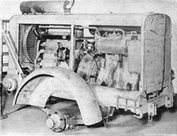
Figure 104.—F.M.A. Air Compressor.