
Chapter Ten

Contents
· Introduction to Building Codes
· Framing According to Code
· Protection from Decay
· Termite Protection
Framers, builders, architects, engineers, and building inspectors alike have contributed to the system of building codes we use today. You should be aware of the codes that apply to the part of the country you are working in, as well as the important features of those codes. This chapter will discuss what you should know about building code requirements.
Introduction to Building Codes
The Evolution of Building Codes
Although carpentry is one of the oldest professions, framing as we know it today didn’t start until 1832 when a man named George Snow wanted to build a warehouse in Chicago. It was difficult to obtain enough large timbers to build the structure using the traditional post and beam method. Being creative (as all good builders and lead framers must be), he cut up the small timbers he had growing on his property into pieces similar to 2 × 4s. He placed them in a repetitive manner, thus creating the first 2 × 4 style walls.
Since then, architects, engineers, builders, building inspectors, and framers have all contributed to the system we use today. Along the way, builders constructed buildings in the way they saw fit. Although this “every man for himself” approach to building gave us structures to live and work in, it did not guarantee that such buildings would last a lifetime, be safe to live and work in, or stand up against earthquakes and hurricanes.
It wasn’t until 1915 that a group of building officials decided they needed a standard. That year, the Building Officials & Code Administrators International (BOCA) was established to bring some uniformity to the systems being used.
The IBC
Two other building code agencies appeared not long after: the International Conference of Building Officials (ICBO), and the Southern Building Code Congress International (SBCCI). All three organizations worked to meet the particular needs of their regions of the country.
In the year 2000, these agencies combined their codes to create one common code that would cover the entire country. This code is divided into two books: the International Residential Code (IRC), which covers all one- and two-family dwellings and multiple single-family dwellings (townhouses) not more than three stories in height, and the International Building Code (IBC), which covers all buildings. Separating the code in this way makes it easier to find the information you need. If you are building only houses, duplexes, or townhouses, you would go straight to the IRC.
There are two ways to comply with the code. The prescriptive method, most commonly used, gives specific requirements (such as how many inches on center to space the framing lumber) to build walls that are acceptable. The performance method tells us how a person can determine the strength of a wall using properly stamped, graded lumber, and if that strength meets the minimum code requirements.
Because the prescriptive system is most commonly used, it is the one we’ll cover here. It applies to conventional construction otherwise known as platform or balloon framing, which has been developed over the years on job sites, and has been tested and standardized. Prescriptive code requires no “engineering” design by a registered professional, as long as the project is built in compliance with the International Residential Code (IRC) or International Building Code (IBC).
(Note that with a performance-rated system, you will have a set of plans that you must follow to the letter. These plans come with structural components that must be used exclusively with the plans. Performance-rated codes require design by a registered professional who must specify in accordance with the IRC or IBC.)
A Framer’s Code Responsibility
Although it may seem that the codes are written for lawyers instead of framers, framers must be sure that their work complies to code. Note that some areas of the country may not be covered by a statewide, town, city, or county code. (Counties have historically been the jurisdictions controlling code establishment and enforcement.) Note, too, that code-writing organizations are not government agencies, so codes are not enforceable until or unless a government jurisdiction accepts the codes and makes them part of local law.
Code Revisions & Time Delays
Code Revisions
Revisions are important to keep in mind when working with codes. Codes are normally updated annually, and revised versions are published every three years. Typically, the revisions are not major, but it is important to know which code you must comply with. On some jobs the plans will indicate which codes apply. This information can usually be found on the cover page or with the general specifications in the plans. If the applicable code is not shown on the plans, ask the builder, owner, or whoever acquired the building permit about the code.
Time Delays
Another thing to keep in mind is the time that may elapse between when the code-writing organizations publish a revised code and when that code edition becomes the ruling code on the job you are framing. There are delays between when the code agencies certify the new codes and when the local government agencies review and approve them. There can also be delays between the date the permit is issued and the date the job is framed. It is not unusual to be working on plans that are three or four years or more behind the current building code. Although you have to comply with the code that is specified on the plans or that was used when the building permit was approved, you should also understand the current code because, in general, additions to the codes are improvements, or ways that contribute to making a building stronger. After every major earthquake or hurricane, codes have been adjusted and upgraded. By using the latest code, you can feel confident that you are framing with the latest construction knowledge.
Latest Code Used in This Book
This book uses the 2009 edition of the IBC and IRC to explain the major features of codes related to framing. These include structural requirements and life safety issues, and the spreading of fire. Although the code books may seem big and intimidating when you first see them, the number of pages that deal with framing are relatively few.
The following IBC & IRC Framing Index table is a handy list of all the framing sections of either code you might need. It was compiled based on the 2009 code books. In the IRC, the framing information can be found primarily in 4 of the total 43 chapters. In the IBC, 3 of the total 35 chapters deal with framing. The IRC framing chapters are 3, 5, 6, and 8. The IBC chapters containing framing information are 10, 12, and 23.
Important Code Features
What follows are key features of the code, and illustrations presented in a framer-friendly way. If you do a lot of framing, it’s a good idea to have a copy of the code book available for reference.
The three major categories used in the IBC are:
· Use and occupancy classification
· Fire-resistance-rated construction classification
· Seismic design categories
In the IBC, the seismic design categories are based on their seismic use group. The categories are A, B, C, D, Da, E, and F. Although they are similar to the categories in the IRC, there are some differences.
IBC IRC Framing Index


Framing According to Code
Floor Framing
Following are the code requirements and instructions related to floor framing:
· Double joists are required under parallel bearing walls.
· If pipes penetrate floors where double joists are required, the joists must be separated and have full-depth, solid blocks at least every 4’ along their length.
· Bearing for joists must be 1½″ minimum on wood or steel, and 3″ minimum on concrete or masonry.
· Where joists lap, there must be a minimum lap of 3″ or a wood or metal splice of equal strength.
· The ends of joists must be kept from turning by using 1½″ full-depth solid blocking or by attaching them to a header, band, rim joist, or adjoining stud.
· Full-depth, solid blocking is required at intermediate supports in IRC seismic design categories D1, D2, and E. (See seismic maps in Chapter 9.)
· Bridging at 8’ O.C. is required only when joists are larger than 2 × 12, and both edges are not held in line, as with plywood floor sheathing and drywall sheathing, or if thicker than 2″ nominal.

The “Floor Joists—Anchor or Ledger” illustration below shows how joists framing into girders must be supported by framing anchors or a 2 × 2 or larger ledger.
Engineered wood products, such as I-joists, can be notched according to the manufacturer’s specifications. (See Chapter 8 for more on engineered wood products.)
The “Framing Floor Openings” illustration shows the following code requirements and instructions related to framing around openings in floors.
· If the header joists are more than 4’, the header joists and trimmer joists should be doubled.
· If the distance from the bearing point of a trimmer joist to the header joist is more than 3’, the trimmer joists should be doubled.
· If the header joist is greater than 6’, hangers must be used.
· If the tail joists are more than 12’, use framing anchors or a 2 × 2 ledger.
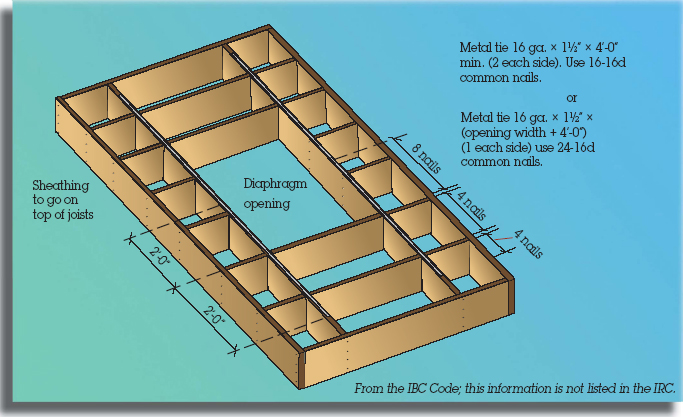
The “Seismic Floor Opening Framing” illustration shows what to do if you are building in IRC seismic design categories B, C, D, or E and the opening is greater than 4’ perpendicular to the joists. In such cases, you must provide blocking beyond the headers, and metal ties must be used to connect the headers with the blocks.
Floor Joists—Anchor or Ledger

Floor Joists—Drilling & Notching Requirements

Framing Floor Openings

Seismic Floor Opening Framing with an Opening Greater than 4' Perpendicular to the Joists
Wall Framing
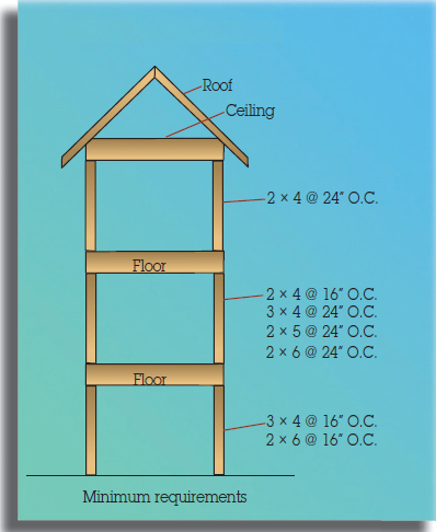
Stud spacing should be shown on the plans, but it is still good to be familiar with the code limitations. For 2 × 4 studs less than 10 feet tall, the maximum stud spacing is 24″ O.C., provided the wall is supporting one floor or a roof and ceiling only. For the support of one floor, a roof, and ceiling, 16″ O.C. is the maximum. To support two floors, a roof, and a ceiling with a maximum spacing of 16″ O.C. and height of 10’, a minimum of 3 × 4 studs must be used. If studs are 2 × 6, a wall can support one floor, a roof, and ceiling at 24″ O.C., or two floors, a roof, and ceiling at 16″ O.C. Again, this stud spacing only applies to walls that don’t exceed 10’ in height. (See “Stud—Spacing and Size” illustration.)
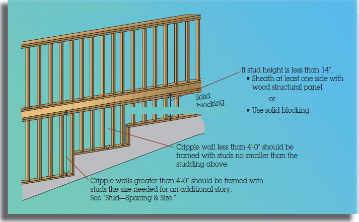
Cripple walls less than 4’ in height should be framed with studs at least as big as those used in the walls above them. If the cripple walls are higher than 4’, then the studs need to be at least the size required for supporting an additional floor level (as described in previous paragraph). (See “Foundation Cripple Walls” illustration.)
Stud—Spacing and Size
Foundation Cripple Walls
Double plates are needed on top plates for bearing and exterior walls. The end joints of the top plates and double plates should be offset by at least 48″. The IRC allows a 24″ offset at nonstructural interior walls. The end joints need to be nailed with at least eight 16d nails or twelve 3″ × 0.131” nails on each side of the joint. A single top plate may be used if the plates are tied together at the joints, intersecting walls, and corners with 3″ × 6″ galvanized steel plates or the equivalent, and all rafters, joists, or trusses are centered over the studs. (See “Walls, Top and Double Plate” illustration.)
Allowable drilling and notching is different for bearing or exterior walls, and for non-bearing or interior walls. Bearing or exterior walls can be notched up to 25% of the width of the stud and drilled up to 40% of the stud provided that the hole is at least 5/8″ away from the edge. With interior non-bearing walls, the percentages are 40% for notches and 60% for drilling. (See “Drilling & Notching Studs, Exterior & Bearing Walls” and “Drilling & Notching Studs, Interior Nonbearing Walls” illustrations later in this chapter.)
Header sizes for exterior and bearing walls should be specified on the plans. For nonbearing walls, a flat 2 × 4 may be used as a header for a maximum of up to 8’ span where the height above the header to the top plate is 24″ or less. (See “Header for Nonbearing Walls” illustration later in this chapter.)
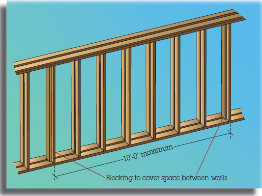
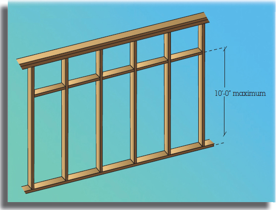
Fireblocking refers to material you install to prevent flames from traveling through concealed spaces between areas of a building. The location of fireblocks is sometimes difficult to understand. It helps to think of where flames would be able to go. A 1½"-thick piece of wood can create a fireblock. If you place a row of these blocks in a wall, you create a deterrent for the vertical spread of fire. Vertical and horizontal fireblocks are required in walls at least every 10’. (See “Fireblocking Vertical” and “Fireblocking Horizontal” illustrations later in this chapter.)
In a “party wall” construction, where you have two walls next to each other, you can create a fireblock by installing a stud in the space between the studs in the two adjoining walls. This creates a vertical fireblock. Note that ½″ gypsum board can also be used to create this type of fireblock.
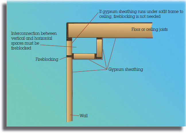
Fireblocking is required between walls, floors, ceilings, and roofs. Typically, the drywall covering creates this fireblock. If it doesn’t, then fireblocking is needed. Where fireblocking is required behind the ledger, it can be installed at the interconnections of any concealed vertical and horizontal space like that which occurs at soffits, drop ceilings, or cove ceilings. (See “Fireblocking at Interconnections” illustration later in this chapter.)
Stair stringers must be fireblocked at the top and bottom of each run and between studs along the stair stringers if the walls below the stairs are unfinished.
Walls, Top and Double Plate

Drilling & Notching Studs, Exterior & Bearing Walls

Drilling & Notching Studs, Interior Nonbearing Walls

Header for Nonbearing Walls

Fireblocking Vertical
Fireblocking Horizontal
Fireblocking at Interconnections
Wall Bracing
Wall bracing is needed to keep buildings from falling. Sheathing the exterior walls is a typical way to provide bracing. The architect, engineer, or whoever creates the plans will specify when any special bracing is needed. Although you don’t need to know everything about wall bracing, it is good to have a basic understanding of it.
Two common exceptions to these methods are: (1) the short wall often used for garages, and (2) the 24″ wide corner wall. Note that cripple walls have their own requirements.
The IBC states that braced wall panels must be clearly indicated on the plans. However, this is not always the case in the real world. Although shear walls are usually marked on the plans, braced wall panels often are not.
Anchor Bolts

The IBC and IRC contain a table that shows braced wall panel limitations and requirements. The limitations are related to the seismic design category, and to how many stories are built on top of the walls.
Where braced wall lines rest on concrete or masonry foundations, they must have anchor bolts that are not less than ½″ in diameter or a code-approved anchor strap. The anchor bolts or straps should be spaced not more than 6’ apart (or not more than 4’ apart if the building is over two stories).
Each piece of wall plate must contain at least two bolts or straps. There must be one between 4″ and 12″ from each end of each piece. A nut and washer must be tightened on each bolt. In IBC seismic design categories D, E, and F, engineered shear walls require 0.229″ × 3″ × 3″ plate washers. In IRC seismic design categories D0, D1, D2, and E, braced walls require 0.229″ × 3″ × 3″ plate washers. (See “Anchor Bolts” illustration.) These requirements also apply to townhouses in seismic design category C.
The eleven basic construction methods for braced wall panels are as follows:
1. LIB—Let-in-bracing
2. DWB—Diagonal wood boards
3. WSP—Wood structural panel
4. SFB—Structural fiberboard sheathing
5. GB—Gypsum board
6. PBS—Particleboard sheathing
7. PCP—Portland cement plaster
8. HPS—Hardboard panel siding
9. ABW—Alternate braced wall
10. PFH—Intermittent portal frame
11. PFG—Intermittent portal frame at garage
Rafter Framing
Ridge boards must be at least 1″ nominal in width and must be as deep as the cut end of the rafter. Hip and valley rafters must be at least 2″ nominal and must be as deep as the cut ends of the rafters connecting to the hip of the valley. Gusset plates as a tie between rafters may be used to replace a ridge board.
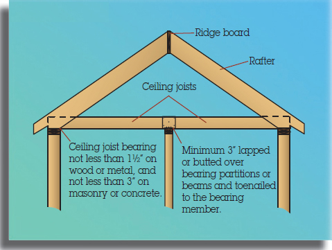
Rafters must have a bearing surface similar to that of joists at their end supports. Bearing needs to be 1½″ on wood or metal and not less than 3″ on masonry or concrete.
Drilling and notching have the same limitations for rafters as they do for floor joists. (See “Rafter Drilling & Notching” illustration.)
To prevent rotation of rafter framing members, lateral support or blocking must be provided for rafters and ceiling joists larger than 2 × 10s.
Bridging must be provided for roofs or ceilings larger than 2 × 12. The bridging may be solid blocking, diagonal bridging, or a continuous 1″ × 3″ wood strip nailed across the ceiling joists or rafters at intervals not greater than 8’. Bridging is not needed if the ceiling joists or rafters are held in line for the entire length with, for example, sheathing on one side and gypsum board on the other.
When rafters are used to frame the roof, the walls that the rafters bear on must be tied together by a connection to keep them from being pushed out. If these walls are not tied together, then the ridge board must be supported by or framed as a beam in order to support the ridge. Ceiling joists are typically used to tie the walls together. The ceiling joists must be tied to the rafters, the walls, and any lapping ceiling joists. (See ceiling joists.)
Rafter Drilling & Notching


Ceiling Framing
Ceiling joists must have bearing support similar to that of rafters. The bearing must be 1½″ on wood or metal, and not less than 3″ on masonry or concrete.
The most important thing to remember about ceiling joists is that if they are used to tie the rafter-bearing walls at opposite ends of the building, then those joists must be securely attached to the walls, to the rafters, and to each other at the laps. If the ceiling joists do not run parallel with the rafters, an equivalent rafter tie must be installed to provide a continuous tie across the building.
The IRC calls for a minimum ceiling clearance of 7’. The IBC requires 7′-6″ with the exception of bathrooms, kitchens, laundry, and storage rooms, where it can be 7’.
There are three exceptions to this rule. First, beams or girders can project 6″ below the required ceiling height if they are spaced more than 4’ apart. The second exception is for basements without habitable spaces. These may have a minimum height of 6′-8″ and may have beams, girders, ducts, and other obstructions at 6′-4″ in height. The third exception is for a sloped ceiling. Fifty percent of the sloped ceiling room area can be less than the minimum ceiling height. However, any portion of the room less than 5’ in height cannot be included in figuring the room area. (See “Ceiling Heights” illustration later in this chapter.)
Truss Framing
Trusses are an engineered product. This means that an engineer or design professional must design them for each job to form a roof/ceiling system. Components and members of the trusses should not be notched, cut, drilled, spliced, or altered in any way without the approval of a registered design professional.
Ceiling Joists
Attic Access & Ceiling Heights
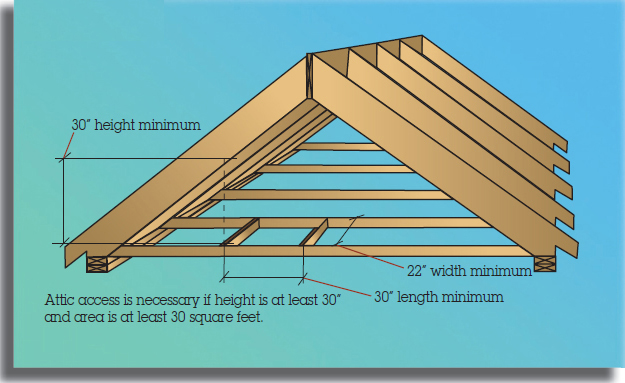
An attic access must be provided if the attic area exceeds 30 square feet, and the height is at least 30″. This opening must be at least 22″ × 30″, and there must be a height of at least 30″ at the access opening. (See “Attic Access” illustration below.)
Attic Access
Ceiling Heights

Stair & Ramp Framing
The width of stairs must be a minimum of 36″ from finish to finish. Handrails may project into the 36″ a maximum of 4½″ on each side. (See “Stairs” illustration.)
Two sets of tread and riser dimensions apply to minimum and maximum requirement. One set is for Group R-3, Group R-2, and Group 4 (houses, apartments, dormitories, non-transient housing). The other is for all other groups. The first set requires a maximum riser height of 7¾″ and a minimum tread depth of 10″, while the second requires a maximum riser height of 7″, a minimum riser height of 4″, and a minimum tread depth of 11″.
Stairs

The variation in riser height within any flight of stairs must not be more than 3/8″ from finish tread to finish tread. The variation in tread depth within any flight of stairs cannot be more than 3/8″ from the finish riser to the nose of the tread.
Headroom for stairways must have a minimum finish clearance of 6′-8″, measured vertically from a line connecting the edge of the nosings.
Handrails for stairs must have a height of no less than 34″ and no more than 38″, measured vertically from a line created by joining the nosing on the treads.
Stairway landings must be provided for each stairway at the top and bottom. The width each way of the landing must not be less than the width of the stairway it serves. The landing’s minimum dimension in the direction of travel cannot be less than 36″, but does not need to be greater than 48″ for a stair having a straight run. (See “Stair Landing” illustration.)
Circular stairways should have a minimum tread depth at a point 12″ from the edge of the tread at its narrowest point of not less than 11″. According to both the IRC and the IBC, the minimum depth at any point must be 6″. (See “Circular Stairs” illustration.)
Spiral stairways must have a minimum width of 26″. Each tread must have a minimum tread width of 7½″ at a point 12″ from the narrow edge of the tread. The rise must be no more than 9½". All treads must be identical. The headroom is a minimum of 6′-6″. (See “Spiral Stairs” illustration.)
Stair Landing

The maximum slope on a ramp is 8%, or one unit of rise for 12 units of run. Some exceptions (where technically infeasible) are available for slope of 1 unit vertical in 8 units horizontal—12-½%. Handrails must be provided when the slope exceeds 8.33%, or one unit of rise and 12 units of run.
The minimum headroom on any part of a ramp is 6′-8″.
A minimum 36″ × 36″landing is required at the top and bottom of a ramp and where there is any door, or where the ramp changes direction. The actual minimum landing dimensions will depend on the building use and occupant capacity. This minimum does not apply to non-accessible housing.
The maximum total rise of any ramp cannot be more than 30″ between level landings. (See “Ramps” illustration later in this chapter.)
Circular & Spiral Stairs

Ramps

Ventilation
Ventilation is required so that condensation does not occur on the structural wood, causing dry rot and the deterioration of the building. Cross ventilation is required in crawl spaces, attics, and in enclosed rafter spaces. In rafter spaces between the insulation and the roof sheathing, there must be at least 1″ clear space.
The total area of the space to be ventilated cannot be more than 150 times the size of the area of the venting. (Both are measured in square feet.)
Protection from Decay
Moisture and warm air are catalysts of fungus, which causes dry rot that can destroy a building. In addition to calling for ventilation to control moisture, the code also requires decay-resistant wood wherever moisture can come in contact with structural wood. Some areas of the country are more conducive to decay than others. The code requires naturally durable wood or preservative-treated wood in the following situations:
· Wood joist or the bottom of the wood floor structure if less than 18″ from exposed ground. (See “Joists & Girder Protection” illustration.)
· Wood girders if closer than 12″ from exposed ground.
· Wall plates, mudsills, or sheathing that rest on concrete or masonry exterior walls less than 8″ from exposed ground. (See “Exterior Wall Decay Protection” illustration.)
· Sills or sleepers that rest on a concrete or masonry slab in direct contact with the ground, unless separated from the slab by an impervious moisture barrier. (See “Decay Protection from Slab” illustration later in this chapter.)
· The ends of wood girders entering exterior masonry or concrete walls having less than ½″ clearance on tops, sides, and ends. (See “Ends of Girders in Masonry or Concrete” illustration.)
· Wood furring strips or framing members attached directly to the interior of exterior concrete or masonry walls below grade.
· Wood siding less than 6″ from exposed ground.
· Posts or columns that support permanent structures and are themselves supported by a masonry concrete slab or footing in direct contact with the ground. (See “Post and Column Decay-Resistant Wood” illustration.)
Joists & Girder Protection

Exterior Wall Decay Protection

Ends of Girders in Masonry or Concrete

Decay Protection from Slab

Post and Column Decay-Resistant Wood

Nailing
Nailing is one of the most important parts of framing. Table 2304.9.1, Fastening Schedule (see IBC Nailing Table), is taken directly from the IBC 2009. The table shows use of alternate nails. The 3″ × 0.131″ nail is the most common nail gun nail used for framing.
IBC Nailing Table


Termite Protection
Framers in many areas of the country have to be concerned about protection against termites. Pressure preservative-treated wood, naturally termite-resistant wood, or physical barriers can be used to prevent termite damage. The following map shows termite infestation probability by region.
Termite Infestation Probability

Conclusion
An important part of your job as a lead framer is being aware of the building codes that apply to framing in your part of the country. You should be aware of how to use the code and of any revisions to those codes. Although locating information you need in the code books is often the hardest part of using the codes, the “Framing Index” at the beginning of this chapter should make this easier for you. It’s a good feeling to know that you have framed a building the way it’s specified according to code.