Chapter Nine
Contents
· The Strength of Good Framing
· Understanding Structural Loads
· Building Code Load Requirements
· Regional Considerations
· Framing Details
· Hold-Downs
· Positive Placement Nail Guns
Buildings are naturally affected by the forces of nature, and also by artificial forces. Elements such as gravity, wind, snow, earthquakes, retained soil, water, impact by an object, and mudslides can all have negative effects on a building.
This chapter will give you a basic understanding of the forces that affect buildings, and some helpful information on the framing methods used to resist those forces.
Although you may not be responsible for designing structural requirements for buildings, it is important to have some understanding of a building’s structural loads. When you are aware of the reasons behind the decisions engineers and architects make, it is easier to interpret the plans, and to make sure that the structure is built accordingly.
The Strength of Good Framing
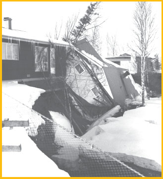
The forces of nature can have devastating effects on buildings. The following photo shows an example of how destructive the elements can be. This photo is quite dramatic; you can see that the ground literally fell out from under the house. But the photo also shows the strength of good framing—the house stayed together even though the ground collapsed under it.
The house stayed together even as the ground fell from under it.
Source: APA, The Engineered Wood Association
Understanding Structural Loads
As the forces of nature contact a building, they travel throughout seeking a weak link. Ultimately, if a weak link is not found, the force or energy will be transferred to the ground, which will absorb the force. Each component of the building must be strong enough to transfer the load in a path to the ground. The components are:
· Foundations
· Walls
· Floors
· Roofs
· Connections
To achieve the strength needed, a building’s walls, floors, and roof must work together as a unit. The vertical elements that are used to resist forces are commonly called shear walls, and the horizontal elements (like floors and roofs) are called diaphragms. The path of energy to the ground is called the load path. The diagram on the next page shows the load path for transferring the forces to the ground.
Building Code Load Requirements
Conventional and nonconventional codes regulate the strength needed in the walls, floors, roofs, and connections to resist the forces on buildings. The conventional code describes a prescriptive standard to resist the forces. The standard applies to simple buildings using common construction methods. The nonconventional code is a performance-rated system and provides non-prescriptive engineering guidelines that can be applied to more unusual or more difficult buildings.

Prescriptive Format
The prescriptive format has specific requirements, such as the size of studs needed or the type of wall bracing. If you build the structure following these requirements, then the building meets the minimum code standards for a safe building. The prescriptive codes are covered in more detail in Chapter 10.
Framers meet prescriptive code requirements on a regular basis, sometimes without even knowing it. As they brace their walls, block and nail their floor system, nail their walls to the floors, and bolt the building to the foundation, they are creating a load path that transfers the forces of nature to the ground—in ways that are prescribed by the code.
Non-Prescriptive Code
The performance, or non-prescriptive, code provides for free design, as long as it stays within certain code standards. Performance designing is different for each building, and the engineer or architect must specify and detail all aspects of the design.
Forces on Buildings
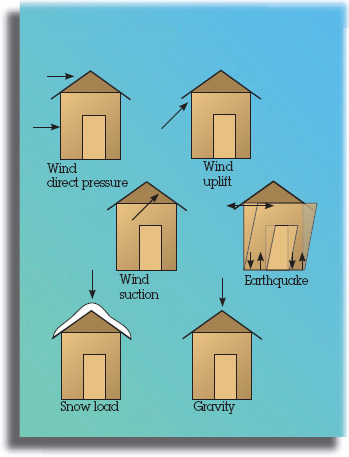
A special design might be needed because a building is in a high-earthquake or a high-wind zone, because it requires large open spaces or window walls, or to resist other forces. The most common forces affecting buildings are shown in the illustration “Forces on Buildings.”
Regional Considerations
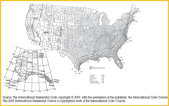
Different forces affect buildings in the various parts of the country. Builders have to worry about earthquakes in California, high winds in Florida, and snow loads in Colorado. It’s easier to understand the architect’s or engineer’s plans if you are aware of these factors. The following maps give you an idea of some of the areas of the country that suffer most from the effects of earthquakes, winds, and snow loads.
Framing Details
The most common framing details can be broken down into three categories.
· Shear wall construction
· Diaphragm construction
· Connections
Each of these categories is covered in this section, including important points for framing.
Shear Wall Construction
The factors that affect the strength of any shear wall are:
· The size and type of material used for the plates and studs.
· The size and type of material used for the sheathing.
· Whether one side or both sides have sheathing.
· The nail sizes and patterns.
· Whether or not there is blocking for all the edges of the sheathing.
Engineers and architects are free to use any system they prefer, as long as they can prove that it meets the minimum strength requirements. The easiest and most common method is using the code book tables that provide accepted values for walls with given resistance capabilities. (Table 2306.3 in the 2009 International Building Code (IBC) shows these values.)
Basic wind speeds for 50-year mean recurrence interval
Ground snow loads for the United Stations (lb/ft2)

Seismic Map of Continental U.S.

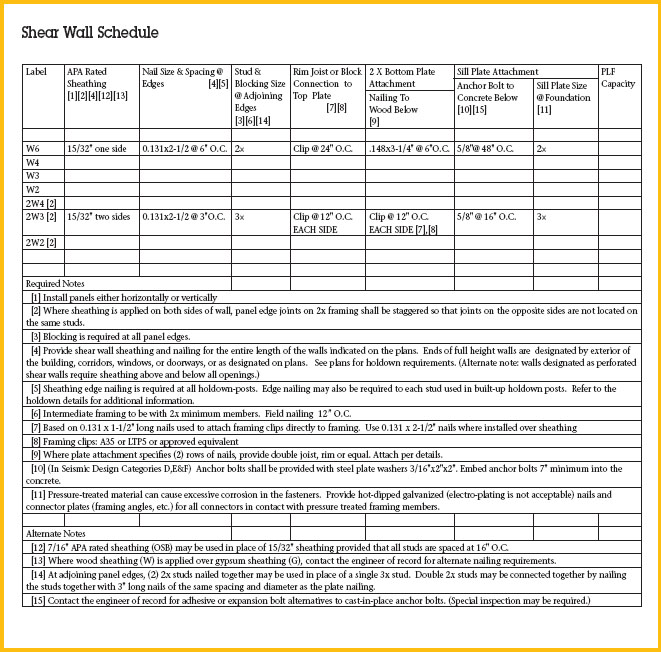
If there are many shear walls in a building, the engineer usually creates a schedule from a code table to show the wall requirements. Unfortunately, there is no standard for labeling shear walls, so the schedules made by the engineers may all be different. They do, however, usually have common components. You will need to study the shear wall schedule on the plans to understand all the components that apply to framing.
Refer to the Shear Wall Schedule table later in this chapter for an example. It is an easy one to use because the labels also identify the nailing pattern and the type of sheathing. It was developed by the framing council in the state of Washington.
Important Points for Shear Wall Framing
1. Stud sizes—Specified nailing patterns may require changes in the stud sizes. There are three conditions where 3x studs are required for nailing adjoining sheathing edges. A fourth condition is required in seismic design category D, E, or F.
· If the edge nailing is 2½″ O.C. or less.
· If there is sheathing on both sides of the wall, the adjoining sheathing edges fall on the same stud on both sides of the wall, and the nailing pattern is less than 6″ O.C.
· If 10d (3″ x 0.148″) nails are used with more than 1½″ penetration, and they are spaced 3″ or less O.C.
· (For seismic design categories D, E, or F) where shear design values exceed 350 pounds per linear foot.
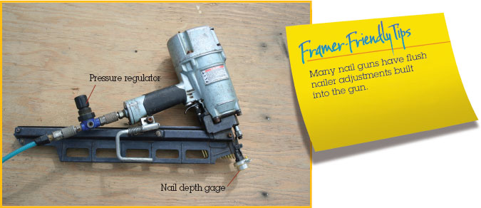
2. Penetration—It is very important that the nail does not penetrate the outside veneer of the sheathing (see “Nail Penetration” illustration.) A pressure regulator or nail-depth gage can be used to make sure this doesn’t happen. (See “Nail Regulator and Flush Nailer” illustration.) The top of the nail should be flush with the surface of the sheathing.
3. Nail size—The nail size may change from wall to wall. Check the specified thickness and length of the nails.
4. Nail spacing—The pattern for nailing the sheathing to the intermediate framing members is usually the standard 12″ on center. It is the edge nailing that changes to increase the strength. If 3× studs are required, then the pattern must be staggered. Make sure that the nails are at least 3/8″ away from the edge of the sheathing.
5. Blocking—The details or shear wall schedule should specify whether blocking is required for panel edges. If the wall is 8’ or less, you can usually satisfy this requirement by running the plywood vertically, so that all the panel edges have backing.

Diaphragm Construction
The strength of diaphragms is affected by these factors:
· The size and type of material used for the joists or rafters
· The size and type of material used for the sheathing
· The direction of the sheathing in relation to the members it is attached to
· The nail sizes and patterns
· Any blocks, bridging, or stiffeners
Nail regulator and flush nailer shown affixed to a pneumatic nailer
Nailing pattern for shear walls utilizing 3× studs

Building codes provide tables for diaphragms similar to those for shear walls. To summarize, the variables used to increase the strength of the diaphragm are the thickness of the sheathing, the size of the nails, the width of the framing member, the nail spacing, and whether or not the diaphragm is blocked.
Diaphragm Framing Tasks of Particular Concern:
· Nail spacing—The nailing pattern for nailing the sheathing to the intermediate framing members is usually the standard 12″ O.C. It is the edge nailing that changes to increase the strength.
· Penetration—The nail must not penetrate the sheathing’s outside veneer.
· Nail size—The nail sizes will vary based on the engineer’s design, or code requirements. Check the specified thickness and length.
· Blocking—It is common to have blocking in the joist space that runs parallel to the exterior walls. It will be detailed on the plans if it is required. Blocking can also be used on the edges of the sheathing.
Nail Penetration

Connections
“Connectors” can refer to beams or other construction elements, but in most cases, connectors are hardware specifically designed for common framing connections. As part of the load path, connections have to be strong enough to transfer the forces of nature.
In the prescriptive code, the connections are made with anchor bolts to the foundation, and with nails to connect floor joists to the plates below them, wall bottom plates to floors, and rafters or trusses to wall plates.
In non-prescriptive design, there are many ways to achieve the required force transfer between the shear walls, diaphragms, and foundation. The most common method involves metal connectors, which are produced by many companies. The Simpson Strong-Tie Company, because of its work in developing, testing, and cataloging connectors, is often referenced in building plans. Simpson Strong-Tie connector catalog numbers will be used in the balance of this book. Please note that substitutes with equivalent strength are available.
There are connectors made for just about every type of connection you can think of. As the framer in charge, however, it is not your job to decide on the type of connector, but rather to use correctly the connector that is specified. The best way to do this is to read the specifications in the connector catalog. Following is an illustration from a Simpson Strong-Tie Catalog, and a good example of instructions for installing hold-downs. You can reference the connectors at www.strongtie.com.
There are different connectors for the variety of different framing details, but only four common areas of connection:
· Foundation
· Wall-to-wall
· Roof-to-wall
· Foundation-to-top-of-the-top-wall
Important Points for Connection Framing
· Install all connectors per catalog instructions.
· Drill holes no more than 1/16″ bigger than bolts.
· Use washers next to wood.
· Fill all nail holes unless using catalog specifications.
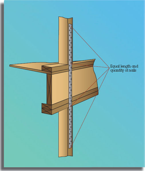
· Know that the connection is only as strong as the weakest side. Make sure to space and nail each side the same. (See “Equal Nailing” illustration later in this chapter.)
· Be aware that some connectors have different-shaped nail holes. The different-shaped holes have different meaning, as illustrated in “Nail Hole Shapes” later in this chapter.
Hold-Downs
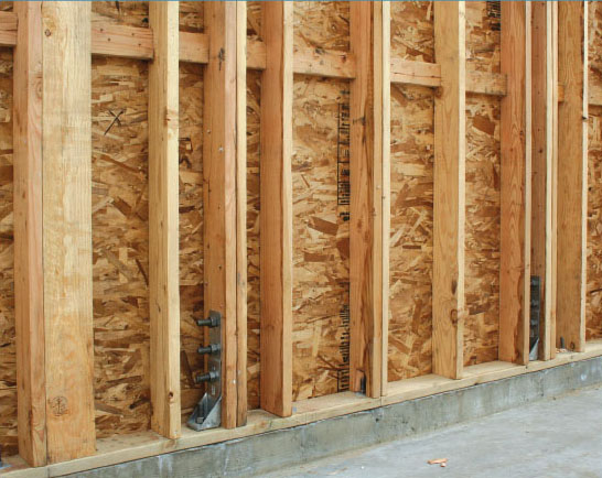
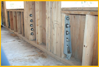
Hold-downs are connections commonly used for foundations, wall-to-wall connections, wall-to-concrete connections, and wall or floor-to-drag strut. Hold-downs are also called anchor downs and tie-downs. They can be difficult to install, but if you plan ahead and install as you go, the job is more manageable. Hold-downs that attach walls to the concrete foundation are typically attached to bolts already in the concrete. These bolts are generally set in place by the foundation crew. Sometimes they won’t be set in the right place.
You will want to locate the hold-down as close to the end of the shear wall as possible. If the bolt is already in the concrete, you will have to locate a hold-down on either side of the bolt. When considering the location, be aware of how it relates to what is on the floor above it; you don’t want, for example, the hold-down coming up in a door or window. You should also allow enough space to install and tighten nuts and bolts.
When to Install Hold-Downs
Although it is common to wait until the building is framed to install the hold-downs, waiting can also present problems, such as studs that are already nailed in place where you want to install the hold-downs, sheathing that is hard to nail because it may be on the exterior of a second or higher floor, and possible pipes or wires running in the stud cavity.
It is helpful to install the hold-down studs as you build the walls. The layout framer should detail the hold-down studs while detailing the wall plates, and should also drill the plates for the anchor bolt or the threaded rods. If an upper floor is involved, the framer should also drill down through the subfloor sheathing and the top and double plate of the wall on the floor below. The wall builder should drill the studs before nailing them into the wall. When the wall sheathing is installed, make sure it is nailed to the hold-down studs using the same nailing pattern that was used for edge nailing. (See “Hold-Down Nailing” illustration.)

Equal Nailing
Just as a chain is only as strong as its weakest link, this strap and its ability to hold two walls together is only as good as its weakest side.
Nail Hole Shapes

Install the hold-downs and bolts, and washers and nuts, as soon as possible. Note, too, that when installing hold-downs after the walls are built, it is more productive to do an entire floor at one time. If the anchor bolts in the concrete do not extend high enough, a coupler nut can be used to extend the length. (See “Coupler Nuts Can Extend Anchor Bolts” illustration.)
As noted previously, the holes drilled for the bolts attaching the hold-down to the studs should not be more than 1/16″ bigger than the bolts. However, it is acceptable to oversize the holes you drill for the threaded rod that passes between the floors. This will make installation easier without affecting strength. (See “Drill Hole Size for Hold-Downs” illustration.)
Hold-downs
With all nail-on connection hardware, it is important to use the right size nail. Hardware manufacturer’s catalogs indicate nail size appropriate for each piece of hardware. Most catalogs also give some options for nail use.
Hold-Down Nailing

Coupler Nuts Can Extend Anchor Bolts

Drill Hole Size for Hold-Downs

Positive Placement Nail Guns
Earthquakes, hurricanes, and tornados continue to wreak havoc on our wood frame houses and buildings. We will never be able to completely protect against the worst case scenario, however our codes are continually improving so that we can make our buildings stronger. A big part of this improvement has been the addition of connection hardware. Whereas most connections used to be secured by nails, connections needed to establish shear and diaphragm strength are now secured by hardware. Most of this hardware is fastened with nails and in many cases a large number of nails. For example, where a small framing clip may take 12 nails, a four foot strap may take 32 nails, depending on the particular size and type of connector.
Because of all the additional hardware nailing, nail gun manufacturers have come out with positive placement nail guns that are specially made for nailing on hardware. There are different styles but they all use the same nails which are different from standard nail guns. The nails are hardened and come in four sizes which are .131 1−1/2″, .148 1−1/2″, .148 2−1/2″, and .162 2−1/2″. The guns use two methods to find the nail holes in the hardware. One style uses a probe that is placed in the hole, and then the gun directs the nail. In the other style, the nail protrudes so that the nail is placed in the hardware hole before firing the gun.
You need to make sure you use the right nail for the hardware. Each piece of hardware has its own nail requirements. If you use too big a nail you can fracture the steel around the nail hole, and if you use too small a nail you will not develop the appropriate strength needed. Hardware manufacturer specifications note the requirements. For example on the web at strongtie.com, Simpson Strong-Tie Company lists all their hardware with the amount and size of nails needed. There is also a convenient nail replacement chart which lists some nail size substitutions. This is helpful when you are installing hardware that was designed for standard nails but you are using positive placement gun nails. You can find this chart at strongtie.com/products/connectors/nails.asp.

Conclusion
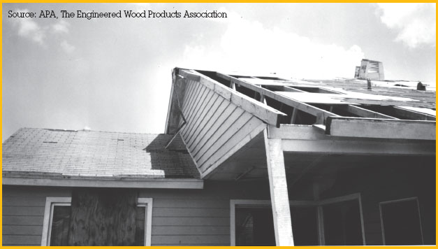
Quality of installation is probably the most important part of framing to withstand the forces of nature. APA (formerly the American Plywood Association, now the Engineered Wood Association) confirmed this fact when it conducted a study of the construction failures in the aftermath of Hurricane Andrew. In the houses they investigated, roofs were the most common failures. Those roof systems most often failed due to lack of proper sheathing nailing.
Wind- and earthquake-resistant framing are important skills for lead framers, and essential to those in susceptible parts of the country. Building codes, along with the designs architects and engineers create to meet code requirements, specify the framing for wind and earthquake resistance. The lead framer must take that information, along with data from connector manufacturers, and ensure that those requirements are met.
Roof failure as a result of Hurricane Andrew