
Chapter Thirteen

Contents
· Checking Exterior Wall Dimensions
· Checking Reference Lines for Square
· Adjusting Reference Lines
· Checking the Building for Level
Certain activities must take place before you begin framing. The dimensions and level of the foundation and slab need to be checked. If they are not perfectly level (which is not unusual), you must determine how far from correct they are, whether they are within tolerances, and what types of adjustments you must make. It is important that the dimensions are accurate, and the building is square before you start. Note, too, that the cabinets, floor covering, drywall, roof trusses or rafters, and much more depend on the measurements being accurate and square.
The four steps to getting started, covered in this chapter, are:
1. Checking the exterior wall dimensions
2. Checking the reference lines for square
3. Adjusting the reference lines to correct dimensions and square
4. Checking the building for level
Checking Exterior Wall Dimensions
If you have the concrete-work reference points handy, getting started will be easier for you. If you don’t, establish reference lines of your own. Be sure to mark these lines well, since you will be using them throughout the job. Using clear marking paint in inverted cans makes it easy to protect your lines on the concrete.
You will want to use the reference lines to find any deviations from plan measurements or any out-of-square parts of the foundation. Start by stringing dry lines that will allow you to measure. The more of the building you can measure from these lines, the more likely you are to find any mistakes. Look at the plans, and string two dry lines perpendicular to each other and covering as long a distance of the building as possible. If you can add two more dry lines, one on each side and opposite to the first two, that will help. (See the “Start-Up” example.) Once you have established your lines, take measurements between the lines and to the major exterior walls in the building. Make a quick footprint of your building, and as you measure the distances, write them down on the footprint. (See “Footprint Sketch Dimensions” example later in this chapter.)
“Laser Dots.” Note: a fifth laser dot would be visible under the back of the laser.

A laser can also be used to establish square lines. The laser will give you dots that you just need to connect. Set the laser up at a convenient position so you will be able to chalk reference lines. Once you have established the lines, use your tape and a 3-4-5 triangle to check for accuracy.
To check the exterior wall dimensions:
1. String dry lines to create reference lines.
· Select lines that are as long as possible.
· Locate line ends at extreme ends of the building.
· Locate lines so that they reference the entire building.
2. Use reference lines to measure the building dimensions.
· Check the exterior wall locations and note any discrepancies.
Checking Reference Lines for Square
To check using four reference lines, measure the two diagonals, then write down the measurements on the footprint you used for measuring the dimensions. If the corner points are set correctly, then the diagonals will be the same length. If the reference dry lines are square, then the diagonals will be the same length. (See “Start-up” example.)
Start-Up Example

If you have only two reference lines to work with, you’ll need to use a triangle to help you check for square. The two reference lines will be “square” with each other if they create a right angle (90°). You can use a 3-4-5 triangle or the Pythagorean theorem to determine whether the two reference lines create a 90° angle. In each case, the three sides (the rise, run, and diagonal) of a triangle must have a certain length relationship for the reference lines to be “square.” Since we can let the two sides of the triangle be the reference lines and make them any length, it is the third line (the diagonal), which will determine if the reference lines are at a 90° angle.
A 3-4-5 triangle works well because as long as one angle is a right angle (90°), and the lines on either side of the right angle (the rise and run) have a relationship of 3 to 4, then the third side (the diagonal) is a 5 in the same relationship.
To use the triangle, use your reference dry lines to replicate a right angle, then create a triangle using the 3-4-5 relationship for the sides. To do this, measure a distance out on each reference string line from the point where the two lines intersect. The measurements of each leg should be a multiple of 3, 4, or 5. Note that the longer the length, the better assurance you have of accuracy. So if you are using a 25’ tape, for example, measure out 20’ on the one side and 15’ on the other side. The distance between these two points—across the diagonal—should be 25’.
The Pythagorean Theorem system sounds a lot worse than it is. If you use a calculator like a Construction MasterPro®, all you need to know is that the three sides of the triangle are represented on the calculator by a “run” button, a “rise” button, and a “diagonal” button. You’ll need to find the length of the third side of the triangle (diagonal) that is required to make the two reference lines square (90°). Enter into the calculator the lengths of the two sides of the triangle that are next to the angle that needs to be 90°. (Press the run button for the one side and the rise button for the other side.) Pressing the diagonal button will give you the length of the third side of the triangle. This length is the distance needed to have the reference lines square and the angle to be exactly 90º.
If the diagonal length is not what it is supposed to be, then write on the footprint how much over or under it is.
To check the reference lines: If you use four reference dry lines, check the diagonals. (See “Square Correction” example.)
· If you use two reference dry lines, use a triangle to check for square.
· Check for and note any discrepancies.
Adjusting Reference Lines
It is common that concrete foundations or slabs are not the exact dimensions that are shown on the plans. These need to be identified and corrected.
Common sense and experience are the best decision-making tools for approaching and correcting errors. Once you have your footprint sketch with the dimensions and square checks on it, you’ll be able to determine if there are any errors.
If a diagonal line is too long, then some of the lines at the end of the diagonal must come in to make the diagonal the right length. (See “Square Correction” illustration.) Check the wall dimensions lines to see which lines can be shortened. Once you’ve determined the best way to make adjustments, speak to the superintendent about your suggestions. Typically, a fix will involve moving the wall in or out on the concrete foundation.
Depending on the finish, there is a certain tolerance that will allow for moving the walls without affecting the appearance. It is common to have finish material that overhangs the foundation, so moving the wall out slightly may not be noticeable. It is also common to have the sheathing on the outside of the foundation, so that if the wall needs to come in, it can be adjusted in the thickness of the sheathing without affecting the look of the finish.
If corrections would cause visible errors in the finished building, then consider alternative measures. An example of a visible error would be if the concrete finish wall sticks out past the siding on the finished exterior wall. There are three methods that can be used to address errors in the foundation. These are as follows:
· Correct the foundation wall. This is the best solution, but often cost-prohibitive.
· Change the dimensions of the building. This is easy, but very often causes problems later on. Make sure to check that the change does not affect truss span if using roof trusses. Also, check to see that the change does not affect dimensions of items such as bathtubs or cabinets. If a change is made, make sure it is made on all copies of the plans.
· Do not correct the errors. Correcting the errors might cause more problems or imperfections in the building than the errors will.
Square Correction

The “Footprint Sketch Dimensions” illustration is made on the job site. It will help determine how to best adjust your reference lines to make the building square. In this example, four dry lines are established to form a square. The diagonal distances that should be the same are then checked. Because they are different, the reference lines will need to be moved to make the diagonals the same. By comparing the actual and the planned dimensions of the walls that the reference lines are measured from, you can determine which reference lines should be moved. When you move a reference line, the other lines are affected.
If you have all the information down on your footprint sketch, you can come pretty close to knowing exactly how much to move each line, and keep making adjustments until you are comfortable with your accuracy. Once your reference lines are established, you can set all the other lines in the building from them. The measurements in circles on the sketch show the distance that the reference lines would be first moved. It is difficult to determine exact amounts because of the proportions, but if you study the footprint for a little while, you can come pretty close.
Checking level using a rotary laser.

Checking the Building for Level
Using a transit or laser is the best way to check for level. A water level can also be used. Once a level foundation has been established, you are ready to cut, drill, and set the mudsill in place.
The foundation and/or slab should be ready for you to start framing when you first arrive. Sometimes, however, this is not the case, and time will be needed to “shoot” (measure using a transit or laser) a foundation and slab. Time must also be allotted to fix any problems in the concrete. It will be your responsibility to check and make a suggestion if you think corrective work is necessary. Start by checking and recording your findings. Record your findings in a way that lets you use the information if you decide the concrete needs corrective work. To record your findings, make a footprint sketch similar to the one you used for dimensions and squaring, and write the readings on the footprint. (See “Footprint Sketch Elevations” later in this chapter.)
To take the measurements using a transit, one framer should hold a tape measure at the spots to be measured, while another framer uses the transit to record the height to the transit line from the concrete. To take a measurement using a rotary laser, one framer records the measure at the spots to be measured using a detector that reads the laser beam.
If you are working with a foundation wall or an existing wall, a rotary laser is efficient because once you have the laser set up, you can just mark the red line and measure up or down from it. If the concrete work is done well, typically within a variance of ¼", then just shooting at strategic locations on the concrete should be sufficient to check for level. If you quickly find out that the concrete is not level, you will need to shoot the concrete every four to eight feet along the walls. Either way, be sure to record the measurements on the footprint sketch. Mark the locations where the measurements were taken. When you start building walls, you will use the measurements in the footprint and the marks on the concrete to determine stud heights. The marks are only made every 4’–8’, because when you are laying out walls, a level can be used to find the heights between the marks. Another way to find the stud heights between marks is to use a chalk line at the top of the wall to rub studs against and mark the heights. (See “Chalk Line at Top of Wall” photo.)
Footprint Sketch Dimensions

Once you have finished a footprint with the elevations marked, you can determine if any corrections need to be made. With the elevations written down, you can show the footprint to the superintendent or owner to let them decide what tolerance they will accept on their building.
If you look at the “Footprint Sketch Elevations” illustration, you will notice that most of the building elevations center around 49¼″ and are within ¼″. The top wall on the sketch, however, appears to be low, with the lowest point at 495/8″. Although 495/8″ is more than 49¼", it actually represents a low point, because the measurement represents the distance from the transit line down to the concrete.
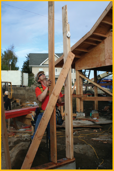
Chalk line at top of wall
Transit line from concrete

On the footprint sketch example, you would probably want to use a height of 49¼″ and recommend adjusting the section of the building that is low.
The Xs on the footprint represent the position of your tape measure when you shoot the height with the transit. Mark the X on the concrete so that when you start building walls, you will have a reference point if your heights need adjustment. Also keep your footprint sketch for this purpose.
Finding Stud Heights for Different Height Foundations
Finding stud heights when the slab or foundation is not level is difficult. It is even more so when the foundation steps up or down to different heights. Using a transit requires you to measure everything from the height that is established when you set the transit. It could be measuring up or down from the transit reading line. It is hard to keep all the numbers in your head when you start adding and subtracting for the different concrete levels and the levels of the foundation.
The best way to find the individual stud heights is to write everything you need for each individual stud down on a piece of paper and figure the stud height from those figures. The illustration “Stud Heights for Different Foundations” illustrates how to do this and includes a “Job Site Worksheet.” Whenever you move the transit, it changes the measurements, so you would have to start over if you did not have all the measurements you need for a particular area. It is easier to finish one area completely before moving the transit.
When there is a foundation wall that is above a slab, it saves time if you chalk a level line on the foundation and then measure the stud heights from this line.
Footprint Sketch Elevations

Conclusion
Before you begin framing, it’s crucial to check your foundation and slab to make sure they are square. Once you have done this, you can move to the next step, the actual framing.
Stud Heights for Different Foundations
