
Chapter Seven

Contents
· Wall Layout
· Joist Layout
· Rafter or Truss Layout
· Roof Layout
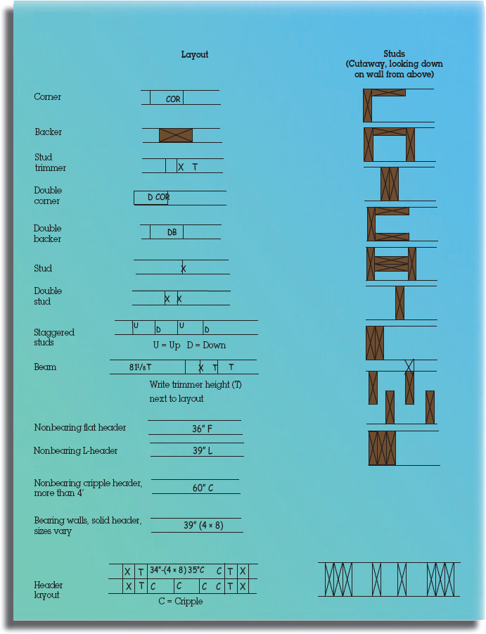
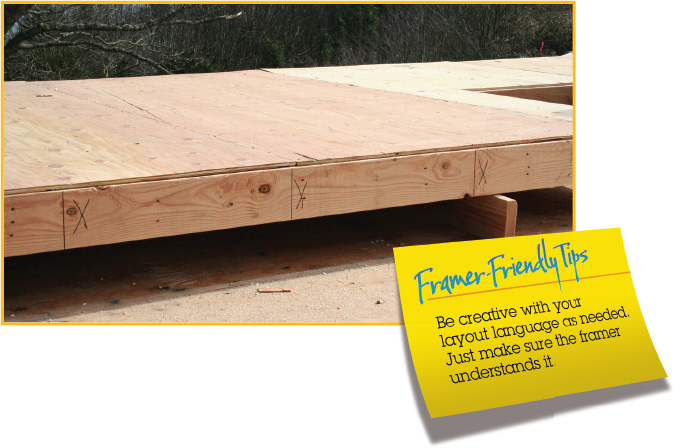
Layout is the written language of the framer. If the lead framer on the job “writes” clearly, then the framers reading the layout will be able to understand and properly perform the work. It’s important to include enough information in the layout so that there aren’t any questions. Layout language has been developed by framers over the years, and there are some variations. The version described in this book is quite typical. Feel free to make any changes that reflect practices in your area. If you need to explain something about the layout that isn’t shown in this chapter, either write it out on the plates in plain language, or explain it to the person who will do the framing.
Layout for framing requires bringing together the desires of the owner, the written instructions of the architect and engineer, instructions from the builder and/or superintendent, and materials from the supplier—then writing these instructions on job-site lumber in a legible manner so that the framers can build the walls, floors, and roofs without continuous interpretation. This chapter describes this process and explains the written words and symbols the lead framer uses.
The approach you use will depend on the size of the job, the area of the country you are working in and, most of all, the style of the person who taught you framing layout. This chapter presents a common style of layout, with some variations. Any style you use is good, as long as the framers can read and understand it, and you have provided all the information they need to frame the building completely.
Language
Wall Layout
On many jobs, the basic skeleton of the walls is built, and then the blocking, hold-downs, and miscellaneous framing are filled in as a later operation. There are some disadvantages to installing miscellaneous framing after the basic framing. For example, you may have to notch around wires and pipes. You may even have to come back and set up a separate operation after you have already left the job site. This chapter describes a system that includes everything possible in the layout, so the walls can be framed, complete, all at one time. To do this takes organization and pre-planning, which includes gathering all the information you need before you do the layout.
Wall plates positioned vertically for layout
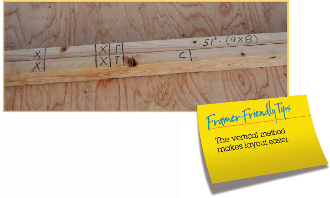
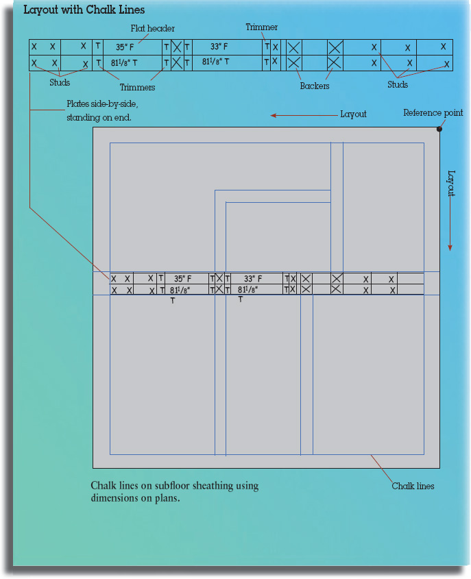
The positioning of the top plate and bottom plate for layout detailing is a variable that depends on personal preference and the type of operations. The plate can be positioned vertically so that the 1½″ width is on top, which makes it easy for marking on the plate. The plate can also be laid flat (horizontally) on top of the chalk lines so that the plates are in the same position as when the walls are standing. This system makes it easy to keep the walls in the proper position, particularly when you have angled walls. A third option (for some exterior walls only) is to position the bottom plate where it will be once the wall is standing, then tack the top plate to it, hanging over the side. This system works well if you want to attach the bottom plate to the floor and then stick-frame the wall.
The layout language varies, but all layout styles are similar. “Language” shows the basic layout language. “Miscellaneous Layout Language Chart” shows additional language. Although the parts of the walls are typically the same in different areas of the country, quite often they are referred to by different names. For example, a backer is also known as a channel or partition. Even the term “layout” can have different meanings. Sometimes layout is understood to be the total process of chalking the lines for the wall locations (snapping), cutting the plates, and writing the layout language on the plates (detailing). It is not important what terms are used, as long as there is clear communication.
Wall layout is the process of taking the information given on the plans and writing enough instructions, in layout language, on the top and bottom plates so the framer can build the wall without asking any questions.
Following is some general information that must be considered before starting. Unless otherwise noted, all layout discussions will assume 2 × 4 studs at 16″ O.C. (on center).
Where possible, we want joists, studs, and rafters to rest directly over each other.
Before layout is started, establish reference points in the building for measuring both directions of layout and use those points for joist, stud, and rafter/truss layout throughout the building.
Check the building plans for a special joist plan or rafter/truss plans indicating layout.
Select a reference point which allows you to lay out in as long and straight a line as possible, and which ensures that a maximum number of rafters/trusses are directly supported by studs.
Wall Layout Steps
1. Spread the top plate and bottom plate together in chalk lines. If a plate is not long enough, cut the top plate to break on the middle of the stud and four feet away from walls running into it.
2. Place plates in position with chalk lines.
3. Lay out for backers from chalk lines.
4. Lay out stud trimmers and cripples for windows and doors.
5. Lay out studs.
Chalking Lines
“Chalking lines” is the process of marking on the subfloor where the walls are to be placed. Red chalk makes a permanent line and is easily seen. Blue chalk can be erased and is good to use if the lines might have to be changed. Using different colors allows you to distinguish between old and new lines.
Before chalking, when possible, check foundation and floor for square. Walls must be square, plumb, and level. If necessary, adjust your chalk lines accordingly.
Measurements for chalk lines are derived from wall dimensions as given in the plans. If the plans show finished walls, be sure to subtract the appropriate amount to get your framing measurements.
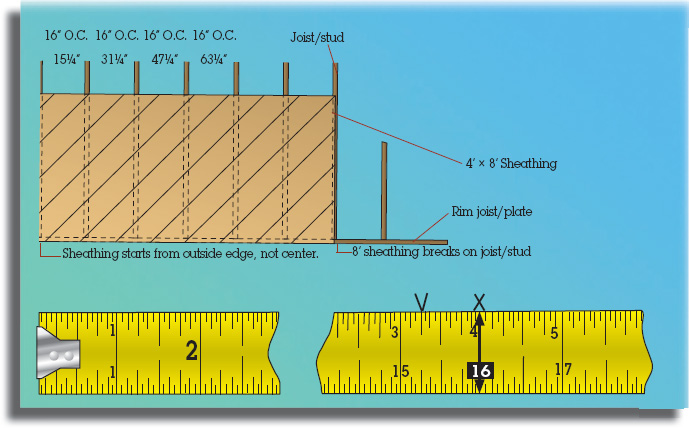
Pulling Layout from a Corner (16″ O.C.)
Pull layout so that sheathing will break in the middle of a joist/stud. Hook tape on the outside edge of rim joist/plate. Pull and locate 16″ on tape, then measure back half the thickness of joist/stud (¾″ for 2× stock) and mark. This puts the layout mark on 15¼". Make an X on the correct side of the layout mark to show the location of the joist/stud. Continue marking in this way for each subsequent 16″ space, thus: 31¼", 47¼", 63¼", etc. Finish by drawing square lines through the mark.
The reason for subtracting the ¾″ is that the 4’ × 8’ sheathing will be installed from the outside edge of the rim joist/plate, not from the center.
Pulling from an Existing Layout (16″ O.C.)
Set end of tape on a layout mark; pull and mark 16″, 32″, 48″, etc. Make an X on the correct side of the layout mark and square a line through the mark. For a long span, set a nail on the existing layout mark, hook tape on the nail, and pull layout.

Miscellaneous Wall Framing Layout
Each building has unique characteristics that require special attention. Hold-downs, shear walls, blocking, backing, special stud heights, and posts are some of the more common miscellaneous framing items. The framing language for these framing items is not well-defined because the operations frequently change and the same ones are not always used. The Miscellaneous Layout Language Chart on the next page gives you an idea of how these framing tasks can be communicated.
Hold-Downs
Hold-downs are probably the most difficult to mark correctly. They vary from location to location and require different studs or posts for connecting.
Wall plates positioned horizontally for layout
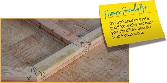
Top plate tacked to bottom plate hanging over edge of concrete for layout

Miscellaneous Layout Language Chart

There are also different types of hold-downs, and each manufacturer has its own identification system. There are, however, four basic styles of hold-downs that you need to show in your wall layout.
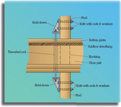
1. Basic hold-down: bolts, nails, or screws to the hold-down post or studs. This type is typically attached to an anchor bolt in the foundation or bolted to an all-thread rod that is connected to a hold-down in the wall below. (See “Hold-Downs with Floor Between” illustration.)
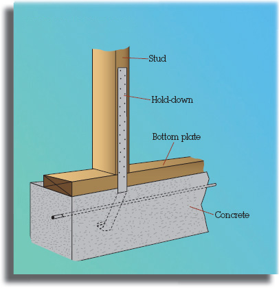
2. Hold-down already embedded in the concrete, which needs only to be attached to the wall. (See “Hold-Down in Concrete” illustration.)
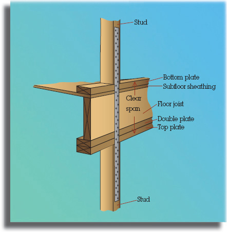
3. Strap used to connect the top of one wall to the bottom of the wall above. (See “Strap Wall to Wall” illustration.)
4. Hold-down that is continuous between all floors from the foundation to the top floor. (See “Hold-Down, Continuous” illustration.)
The difficulty in laying out for hold-downs is knowing what to write on the plates so that the requirement will be easily understood. The best thing to do is to explain to all framers at the beginning of each job what symbols you are using to indicate hold-downs. Use the same language when possible at different jobs. The most common symbol for hold-downs is HD, followed by the number representing the size of the hold-down—for example, HD2 or HD5.
When you are laying out for hold-downs, it’s important to get the layout in the right location. Since the purpose of a hold-down is to connect the building to the foundation, the hold-downs must line up with the anchor bolt in the foundation below them. Hold-downs are typically found at the end of shear walls. Engineers sometimes position hold-downs attached to posts at the ends of walls or within a specific distance from the ends of walls. If that information is not specified, keep the hold-down as close to the end of the wall as possible. If the hold-down anchor bolt is already in the concrete, then you can only position it in two locations—one on either side of the hold-down anchor bolt. (See “Hold-Down Either Direction” illustration.)
Hold-Downs with Floor Between
Hold-Down in Concrete
Strap Wall to Wall
If the epoxy system is specified for installing the anchor bolts later, you have more options. A good rule of thumb is to keep the hold-down within one foot of the end of the wall. However, the shorter the wall, the closer the hold-down should be to the ends of the wall.
When laying out for a hold-down, you want the studs or post to be in the correct position in relation to the anchor bolt or hold-down in the wall. A good way to make sure the distance from the studs to the anchor bolt is correct is to use one of your hold-downs to mark the pattern and location of the studs or post. (See “Hold-Down as Pattern” photo.) If you do not have a hold-down available for this purpose, you can use the manufacturer’s hardware catalog to find the distance from the anchor bolt to the studs.
When you are laying out for the hold-downs on an upper floor, it is helpful to mark the location of the hole to be drilled in the plate and the floor. You have to locate the hole anyway to lay out the studs. By marking its location, you are saving someone else from having to locate it again. It is easiest to go ahead and drill the holes through the floor then, before the walls are built. These holes can be oversized to make alignment easier.
Hold-Down Either Direction

Shear Walls
Shear walls have unique characteristics, but the most common information a framer needs to know about them is the type of sheathing, the edge nail spacing, and the nail spacing for nailing of the bottom plate. This information can usually be found in a shear wall schedule in the plans. The sheathing used is typically either plywood or OSB, commonly identified as “W,” or gypsum, identified as “G.” The edge nailing is designated as a number after the W or G, and the floor nailing as a number before the W or G. An example could be “6W4,” meaning that the bottom plate is nailed at 6″ on center, the sheathing is plywood, and the edge nailing is 4″ on center. The language for shear walls can be written on the plates with the other language, but it is best to also write it on the top of the bottom plate. That way, when you get around to nailing the wall down, the nailing pattern will still be visible.
Hold-down as pattern

Different Length Studs
Some walls will have studs of different lengths. Examples are rake walls or walls where the concrete is not level, and the studs are cut to compensate. In such cases, you will want to write the stud lengths on the plate next to the studs.
Cripples
The cripples to be framed over and under the windows and doors will be laid out on the same layout as the studs. You will mark them with a line and a “C,” and indicate their lengths on the plates—for example, C−251/2″. Mark the cripple height for the cripples that go below the window on the bottom plate, and the cripple height for the cripples that go above the window or door on the top plate.
Blocking
Many kinds of blocks are installed in walls. Some common blocks are fire blocks, medicine cabinet blocks, cabinet blocks, stair rail blocking, curtain rod blocking, and wainscot blocking. The hardest part of laying out for these blocks is getting the right information so you can figure out their location. You might as well find this information before you build the wall, since it is easier and more efficient to install the blocks as you build the walls than afterwards.
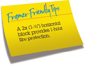
Two basic types of blocks are installed in walls. One is a horizontal block that fills the whole stud space as a fire block does. The other is a vertical block that is flush with one side of the wall. (See “Vertical and Horizontal Blocks” illustration.)
The vertical block is more often used for backing to provide a greater area for attaching fixtures. To position a block in the wall, you need to know if the block is vertical or horizontal, the height of the block, and the size. This information is written with a “B” first, indicating blocking, and then either a “V” or an “H,” indicating a vertical or horizontal position. The height is then written following the V or H, indicating the center height of the block from the subfloor sheathing or the concrete. If the block is vertical you will need to write “U” or “D” indicating up or down, showing which side of the wall the block will be on. If the block is the same width as the studs in the wall, then that is all the information that is necessary. However, if the block is a different width than the wall, then the size of the block should be written before the “B.”
If there are a number of blocks in a row, as is the case with fire blocking, you can just mark one stud space and (with a carpenter crayon) draw a line in both directions to indicate the extent of the blocking.
Hold-Down, Continuous

Backer Layout
Normal backer layout has the layout marks for a backer aligned with the position of the wall that will be nailed into the backer. This isn’t always the case, however. Sometimes it is better to move the backer so it does not line up. For example, you might have a door next to the backer, with only 2½″ between the backer and the rough opening of the door. Instead of having a 1½″ trimmer and a 1″ king stud, you just attach a 1½″ trimmer to the backer and move it over ½".
The best way to mark this on the wall layout is to mark both positions of the backer. The first position is where the backer would align with the wall, and the second is where the backer was moved and where it will be nailed. A good way to distinguish the two positions is to mark over the one line with a carpenter’s crayon (keel or lumber crayon). This layout information will help when the walls are nailed together. It will also help when you are cutting the double plate of the joining wall to overlap. (See “Backer Move” illustration.)
Special Stud Layouts
It is important to be aware of special stud layouts, such as might be required for shower or bathtub center valves. Showers and tubs are typically 30″ wide. Space must be allowed in the middle for the valves. It’s usually easy to find the center and then set a stud 8″ on center each way. (See “Plumbing Studs” illustration.)
Recessed medicine cabinets are another special layout. If they require a 141/2″ rough opening, they could fit between standard 16″ O.C. spaces. More often than not, however, the design requires installation in a particular location that requires special layout.
Backing for Siding
Different types of siding require different types of backing. For example, bevel siding with a wide window will require an extra stud or extra backing along the window to attach the siding.
Vertical and Horizontal Blocks

Backer Move

Plumbing Studs
Structural Support
Often a beam or girder truss, or some other structural member, requires structural support all the way to the foundation, but that support is not shown on the plans. Check and lay out for upper floor structure support when laying out walls.
Location Marks
Another mark you might need to make on your walls is for location. If you have to move the plates to make room to build walls, then you need to mark the location for all the walls to make sure you know where they go when you are ready to build them. It is best to use a crayon and mark a number and an arrow on each plate. The top and bottom plates will be marked with the same number. The arrows will point in the same direction as all the other walls that run in that direction. In addition to marking the plates, mark the number and the arrow on the floor next to the plates. (See “Plate location marks” photo.)
If you are laying out walls on a concrete slab, then you will have to contend with plumbing and electrical pipes. Before you start your layout, notch the bottom plate to fit.
Layout Methods
Use the Correct Order
When you perform the layout, follow a prioritized order. For example, trimmer and king studs for doors and windows take priority over studs. That is because if a stud falls on the location of a trimmer or king stud, then the stud is eliminated. Using a certain order for layout also helps you keep track of where you were if you are pulled off layout and have to come back later to pick up where you left off. The order should be doors and windows first, then bearing posts, backers and corners, then hold-downs—followed by special studs like medicine cabinet studs, then regular studs, and finally miscellaneous framing, such as blocks.
Align Framing Members
It is good practice when laying out studs to align the roof trusses, floor joists, and studs. This is not entirely possible in most cases because the studs are typically 16″ O.C., while the roof trusses or rafters are 24″ O.C. However, you will at least line up every third truss or rafter. If the studs are 24″ O.C., then they need to align with the trusses or rafters. Aligning the studs, joists, and trusses or rafters not only makes good sense structurally, but makes it easier for the plumbers and electricians to run their pipes and wire between floors.
Plate location marks

Consult the Roof and Floor Drawings
To start laying out your studs, you need to know the layout of your roof and floor systems. If you are using dimensional lumber, then you can most likely start the layout for your roof and floor wherever it is convenient. If, however, you are using I-joists or roof trusses, the layout will probably be defined on a set of shop drawings provided by the supplier. You should receive a set of these shop drawings before you start laying out your studs, so that you can align wherever possible. Once you have decided on a starting point for your layout in each direction, use the same layout throughout the building. Although it is not structurally necessary to align nonbearing interior walls with multiple floors, it is helpful to have the studs aligned for the plumbers and electricians.
A Word of Caution
Some production framing techniques speed up the layout process, but be careful, if you use them, not to sacrifice quality. For example, instead of using the X with a line next to it to indicate a stud, a single line can be used to represent the center of the stud. Be careful with this designation, because the studs need to line up with the middle of the wall sheathing. If you figure that you allow 1/8″ for expansion between the sheets of sheathing, that only allows 11/16″ for nailing each side. You cannot afford to be off by even a small amount and still get enough stud to nail to. If you use this system, you also have to be sure that your framers are competent and can align the studs properly.
Other Tasks that Can Be Done Along with Layout
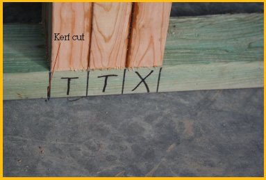
Some items can be attended to while you are performing the layout. One is to cut a kerf in the bottom of the bottom plate at door thresholds when they are sitting on concrete. This kerf (about half the thickness of the plate) allows you to cut out your bottom plate after the walls are standing without ruining your saw blades on the concrete. (See “Kerf cut [threshold cut]” photo.)
Kerf cut (threshold cut)
You can take care of another item while drilling the bottom plate to install over anchor bolts. When the bottom plate is taken off the bolts to do the layout, it can be turned over and accidentally built into the wall upside-down. This problem can be prevented by using a carpenter crayon to mark “UP” on the top of the plate before it is removed from the bolts. Angle walls have the same potential for getting built with the plates backward. You can also mark them as they are being laid out.
Layout Tools
There are some tools that can help with layout, particularly with multi-unit or mass production-type framing. One of these is the channel marker, a template made to assist in laying out corners and backers. Another is a layout stick. The layout stick is 49½″ long and is placed on the plates to act as a jig for marking studs. (See “Channel marker and layout stick” photo.)
Joist Layout
Floor Joist
Joist layout is relatively easy compared with wall layout. It uses the same basic language as walls.
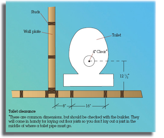
Special layout for joists includes the area under the toilet and shower drain. It is easier to move a joist a couple of inches or even to add a joist than to come back and "header-out″ a joist because the plumber had to cut it up to install pipes. On larger buildings, there may be shop drawings for the floor joists that can be used for your layout. The shop drawings should show the locations of openings and how they should be framed. (See “Joist Layout Language” illustration.)
Channel marker & layout stick

Joist Layout Principles
Joist layout is the process of taking the information given on the plans and writing enough instructions on the top of the rim joist or double plate so the joist framer can spread and nail the joists without asking any questions.
Where possible, we want joists, studs, and rafters to set directly over each other.
Before layout is started, establish reference points in the building for measuring both directions of layout and use those points for joist, stud, and rafter/truss layout throughout the building. Check the building plans for special joist plan or rafter/truss plans indicating layout. Select a reference point which allows you to lay out in as long and straight a line as possible, and which ensures that a maximum number of rafters/trusses are directly supported by studs.
Check plans for openings in the floor required for stairs, chimneys, etc.
Check plans for bearing partitions on the floor. Double joists under bearing partitions running parallel.
Check locations of toilets to see if joists must be headed-out for toilet drain pipes.
Joist Layout Language

Joist Layout Steps
1. Layout for double joist, trimmer joist, and tail joist.
2. Layout for other joists.

Rafter or Truss Layout
Rafter or truss layout, like floor joist layout, is relatively easy compared with wall layout. Sometimes it is helpful to lay out for rafters or trusses on the top of the double plate so that once the wall is standing, the layout will already be done, and you won’t have to do it from a ladder. (See “Rafter layout on walls before the wall is stood up” photo.)
Special layout is often required for ceiling can-lights. Check on necessary clearance to make sure you provide enough room.
Roof Layout
Roof layout is the process of taking the information given on the plans and writing enough instructions on the double plate for the roof framer to spread and nail the rafters or trusses.
Use the same reference points established for floor and wall building for starting layout on the roof.
Roof rafters and trusses are sometimes 24″ O.C. as compared with 16″ O.C. for floors and walls. In that case, only every third truss or rafter will be over a stud.
Before layout is started, check plans for openings in the roof required by dormers, skylights, chimneys, etc.
For roof trusses, lay out according to truss plan, especially for hip-truss packages.
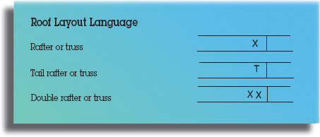
Roof Layout Steps
Lay out for doubles, trimmers, and tail rafters or trusses.
Lay out for other rafters or trusses.

Rafter layout on walls before the wall is stood up
Conclusion
Writing layout is just like writing anything else. If the person reading it understands what you want to say, then you’ve done a good job. When you are done with the layout, take a look at it to make sure you can read it. If your writing is not showing up clearly, you might try a different brand of carpenter pencil. There are different leads, and some write better than others, depending on the condition of the wood. You can also use indelible marking pens, which are especially good on wet lumber.
Review the layout with the framer who will be reading it before he starts. If a framer doesn’t understand your layout, it takes more time for him to try to figure it out than for you to explain it to him. A little extra time spent on layout is usually a good investment. It’s not easy taking information from all the different sources that combine in the construction of a building and making it legible for framing, but if the layout is communicated clearly, it will help the framers do their work in an organized and productive manner.