Chapter Eight

Contents
· Engineered Panel Products
· Engineered Lumber Products
Engineered wood products have been around for years, particularly in the form of plywood, glu-lam beams, and metal-plate-connected wood trusses. I-joists are more recent, as are LVLs (laminated veneer lumber), PSLs (parallel strand lumber), and LSLs (laminated strand lumber).
It is not the intent of this chapter to explain everything there is to know about engineered wood products, but rather to make you familiar with this category of materials, and give you a sense of what to look out for when you are working with them.
Engineered wood products (EWP) fit into two general categories, engineered panel products (EPP) and engineered lumber products (ELP). The first group includes plywood, oriented strand board (OSB), waferboard, and composite and structural particleboard.
The second group includes I-joists, glu-lam beams, metal-plate-connected wood trusses, and structural composite lumber (LVLs, PSLs, and LSLs).
Engineered Panel Products
Engineered panel products are so common that their uses are defined in the building codes. Specific applications vary from job to job, and from manufacturer to manufacturer.
Oriented Strand Board & Waferboard
Most building codes recognize oriented strand board and waferboard for the same uses as plywood, as long as the thicknesses match.
Engineered Panel Products

Working with Engineered Panel Products
When working with any engineered panel products, keep the following guidelines in mind:
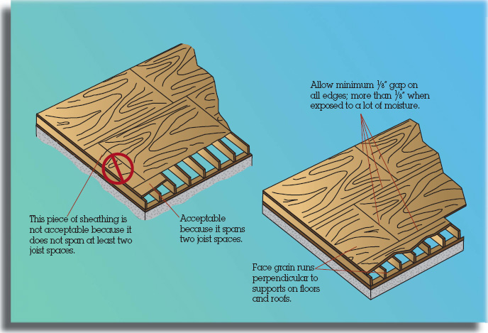
1. On floors and roofs, run the face grain perpendicular to the supports (except with particleboard, which has no grain). See “Using Engineered Panel Products” illustration.
2. Do not use any piece that does not span at least two supports for floors and roofs.
3. Allow a gap of at least 1/8″ on all edges, and a gap of more than 1/8″ if the piece will be exposed to a lot of moisture before the siding is installed. Note that this also applies to walls.
4. Follow manufacturers’ recommended installation directions.
Engineered Lumber Products
I-Joists
I-joists were introduced in 1968 by the Trus Joist Corporation. Although use of this product has grown rapidly over the years, there is still no industry standard for its manufacture and installation. And while the Engineered Wood Association (APA) has established a standard for its members, not all manufacturers are members of APA. Because there is no universal standard, it’s important to use the installation instructions that come in the I-joist package. The package is generally prepared by a manufacturer’s representative working with the architect or designer.
The I-joist package should include installation plans for the building. These plans will be specific to the building you are working on, and will include a material list and accessories. Accessories can include web stiffeners, blocking panels, joist hangers, rim boards, and beams. The plans typically include a sheet of standard details. The following is a list of elements you’ll find in most I-joist packages, and some items to consider when installing them:
Using Engineered Panel Products
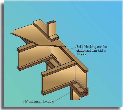
1. Minimum bearing is 1¾". (See “Solid Blocking & I-Joist Minimum Bearing” illustration.)
2. Closure is required at the end of the I-joist by rim-board, rim-joist, or blocking. This closure also serves to transfer vertical and lateral loads, as well as providing for deck attachment and fireblocking, if required. Do not use dimensional lumber, such as 2 × 10, because it is typically 9¼″ instead of 9½". It shrinks much more than the I-joists and will leave the I-joists supporting the load.
3. Interior bearing walls below I-joists require blocking panels or squash blocks when load-bearing walls are above. (See “Interior Bearing Wall Blocking Panel” illustration.)
4. Rim boards are required to be a minimum of 1¼″ in thickness.
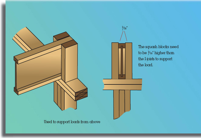
5. Make sure squash blocks, which are used to support point loads (like the load created by a post), are 1/16″ taller than the joists, so that they will properly support the load. (See “Squash Blocks” illustration.)
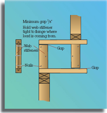
6. Web stiffeners, which are sometimes required at bearing and/or point loads, should be at least 1/8″ shorter than the web. Install web stiffeners tight against the flange that supports the load. If the load comes from a wall above, install the web stiffener tight against the top of the flange. If the load comes from a wall below, the stiffener should be installed tight against the bottom. (See “Web Stiffener” illustration.)
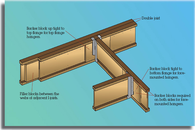
7. Use filler blocking between the webs of adjacent I-joists to provide load sharing between the joists. (See “Filler Blocking & Backer Blocking” illustration.)
8. Backer Blocking is attached on one side of the web to provide a surface for attachment of items like face-mount hangers. (See “Filler Blocking & Backer Blocking” illustration.)
9. I-joists are permitted to cantilever with very specific limitations and additional reinforcement. If the I-joists are supporting a bearing wall, the maximum cantilever distance with additional reinforcement is 2’. If the I-joists are not supporting a bearing wall, the maximum cantilever is 4’. Check the plans for specifics on the cantilever.
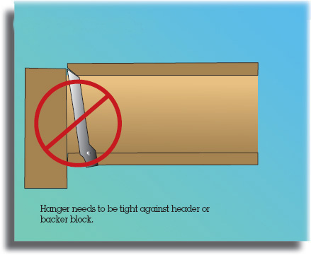
10. Top-flange hangers are most commonly used for I-joists. (See “Top Flange Hanger Tight” illustration.) They come with the I-joist package, but you can also get them from a construction supply store. When installing top flange hangers, make sure that the bottom of the hanger is tight against the backer block or the header. When nailing the hanger into the bottom of the joist, be sure to use the correct length nails. Nails that are too long can go through the bottom flange and force the joist up. (See “Use Right Size Nail” illustration.) When installing hangers on wood plates that rest on steel beams, the hanger should not touch the steel. The distance it can be held away from the steel depends on the plate thickness. Note that hangers rubbing against the steel can cause squeaks. (See “Top Flange Hanger Spacing” illustration.)
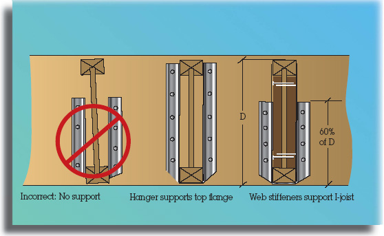
11. Face-mount hangers can be used. Make sure that the hangers are tall enough to support the top flanges of the joists. Otherwise use web stiffeners. (See “Face-Mount Hangers” illustration.) Be sure to use the correct length and diameter of nail.
12. The bottom flange cannot be cut or notched except for a bird’s mouth. At a bird’s mouth, the flange cut should not overhang the edge of the top plate. (See “Bottom Flange I-Joist” illustration.)
13. Leave a 1/16″ gap between I-joists and the supporting member when I-joists are placed in hangers. (See “Gap Between I-Joist & Support” illustration.)
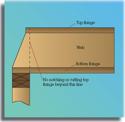
14. The top flange can be notched or cut only over the top of the bearing and should not extend beyond the width of the bearing. (See “Top Flange I-Joists” illustration.)
15. The web can have round or square holes. Check the information provided with the I-joist package. Typically the center of the span requires the least strength and can have the biggest holes. The closer to the bearing point, the smaller the hole should be.
16. When I-joists are used on sloped roofs, they must be supported at the peak by a beam. This is different from dimensional lumber, where rafters may not require such a beam.
In working with residential I-joists, you should be aware that the APA has developed a standard for residential I-joists called Performance Rated I-joists (PRI). This standard shows the span and spacing for various uses for marked I-joists. (See “APA Performance Rated I-Joists” illustration.)
Solid Blocking & I-Joist Minimum Bearing
Interior Bearing Wall Blocking Panel

Squash Blocks
Web Stiffener
Filler Blocking & Backer Blocking
Top Flange Hanger Tight
Use Right Size Nail

Top Flange Hanger Spacing

Face-Mount Hangers
Bottom Flange I-Joist

Gap Between I-Joist & Support

Top Flange I-Joists
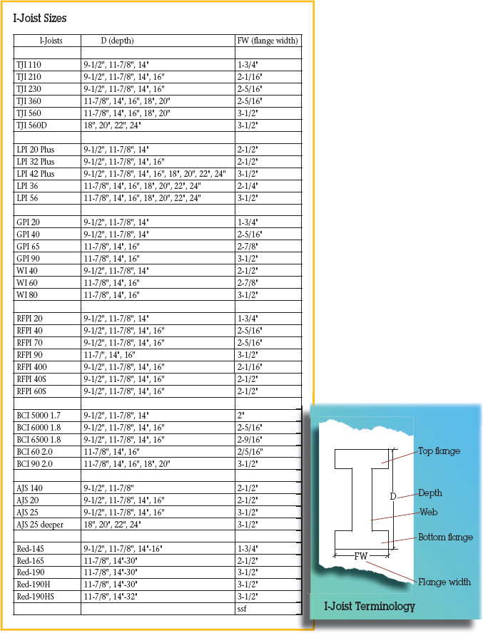
APA Performance Rated I-Joists (PRI)

Glu-Lam Beams
Glu-lam beams are used when extra strength and greater spans are needed. They are usually big, heavy, and expensive, and require hoisting equipment to set them in place. Most often glu-lam beams are engineered for particular jobs. Glu-lam beams are produced by gluing certain grades of dimensional lumber together in a specific order. Many times the pieces are glued together to create a specific shape or camber. If a camber is created, the top of the beam will be marked. Make sure your crew installs it right-side-up.
The expense of glu-lam beams and the time required for replacing one makes it very important that they are cut correctly.
Notching & Drilling
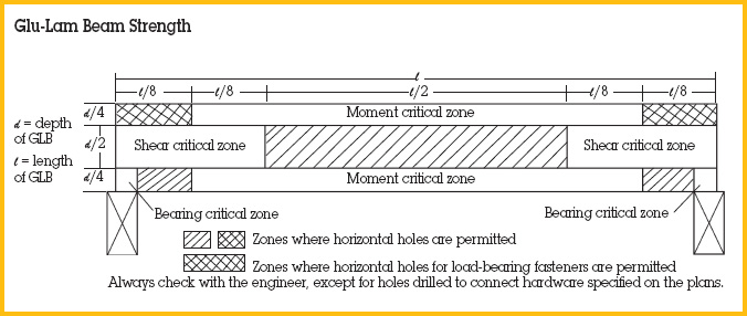
The general rule for glu-lam beams is no notching or drilling without an engineer’s direction. The engineer who determined the strength needed for the glu-lams is the person who will know how a notch or hole will affect the integrity of the glu-lam beam.
The way glu-lam beam connections are made will affect the strength and integrity of the beams. Following the illustrations are examples of correct and incorrect ways to connect glu-lam beams, and some tips for easy installation.
Cut Edge Full Bearing
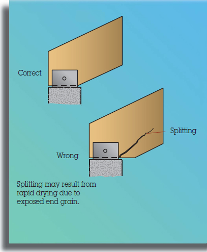
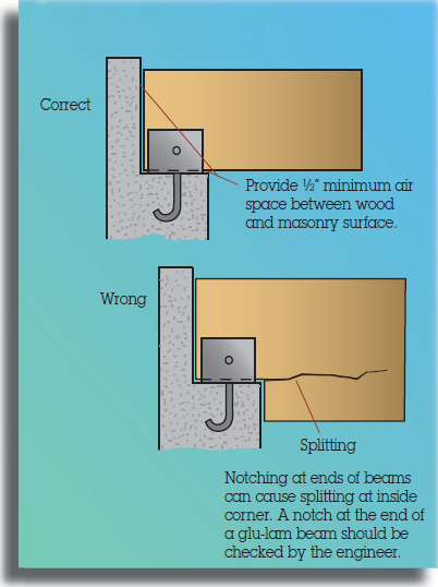
No Notching End of Glu-Lam Beam
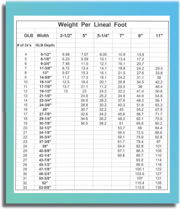
Glued-Laminated Timber Weights for DF-L

Tips for Installing Glu-Lam Beams
· For glu-lam beams that are installed at a pitch and need to have the bottom cut to be level, make sure that the end of the bottom cut closest to the bearing edge receives full bearing.(See “Cut Edge Full Bearing” illustration.)
· Ends of beams should not be notched unless approved by the engineer. (See “No Notching End of Glu-Lam Beam” illustration.)
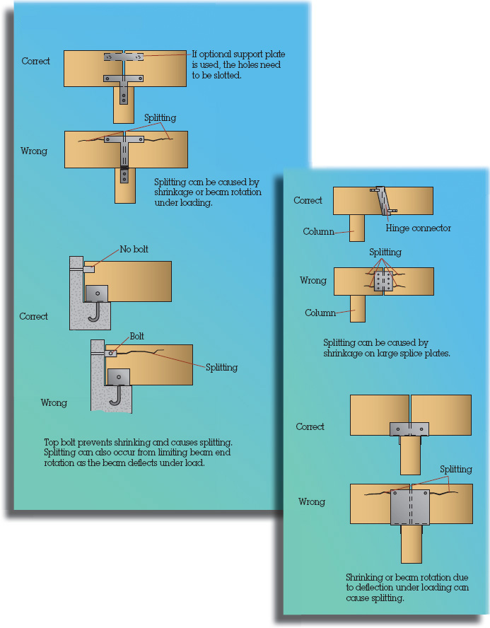
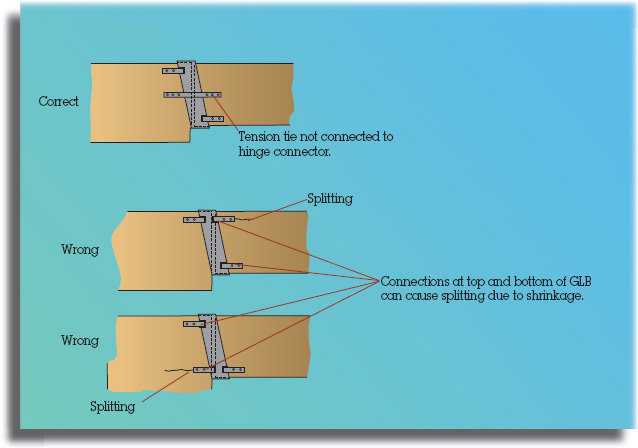
· Glu-lam beams will shrink as they dry out. If the top of the beam is connected in a way that doesn’t allow for shrinkage, the glu-lam beam will split. (See “Glu-Lam Beam Shrinkage” illustration.)
· When a lateral support plate is used to connect two glu-lam beams, the holes should be slotted horizontally to prevent splitting. (See “Lateral Support Plate” illustration).
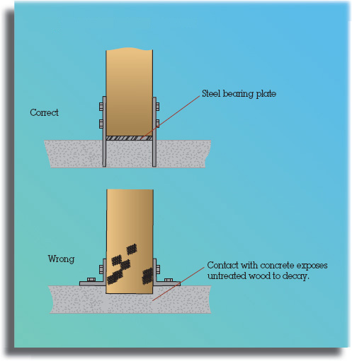
· Glu-lams are also used for posts. It is important to keep them away from concrete, which contributes to their decay. Placing a steel shim under the beam will keep it from touching the concrete. (See “Decay Prevention Next to Concrete” illustration.)
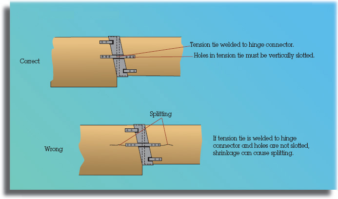
· Hinge connectors should be installed so that they don’t cause splitting of the glu-lam beams. This can be done by using a strap that is independent of the hinge connector, or by vertical slotting the holes in a strap that is connected to the hinge connector. (See “Hinge Connector Slotted Holes” illustration.)
· Glu-lam beams rest on metal post caps that often have a weld or radius in the bottom corner. If you don’t ease the bottom corners of the beam, the beam will sit up in the pocket. Often, the glu-lam beam’s bottom corners are already rounded and won’t need attention.
· In some cases, the sides of the metal post caps are bent in so that the beams will not slide in properly. Check all the sides of the metal post caps before they are installed, so you won’t have a forklift or boom truck and crew standing around waiting while someone labors on top of a ladder to widen the sides of the post cap. (See “Forklift setting glu-lam beams” photograph later in this chapter.)
· Glu-lam beams are often attached to metal caps with bolts. The holes can be drilled either before or after setting the glu-lam beams. If the holes are drilled after the beams are set, use a drill with a clutch. It’s easy to break a wrist or get thrown from a ladder when a ½″ drill motor without a clutch gets caught on the metal.
Glu-Lam Beam Shrinkage
Lateral Support Plate

Decay Prevention Next to Concrete
Hinge Connector Slotted Holes
Hinge Connectors
Metal Plate-Connected Wood Trusses
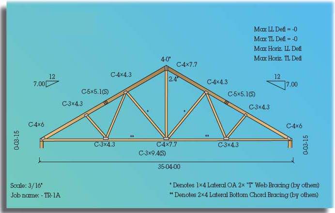
Metal plate-connected (MPC) wood trusses were first used in the early 1950s. Today they are used in more than 75% of all new residential roofs. Basically they are dimension lumber engineered and connected with metal plates. Less expensive than alternative roof systems, these trusses can also span longer distances. The “Pitched Truss Parts” illustration shows the parts of a single pitched truss on the next page.
Because MPC trusses are engineered products, they should never be cut, notched, spliced, or drilled without first checking with the designing engineer.
Building codes require that a truss design drawing be delivered to the job site. The drawings must show, among other things, the layout locations and bracing details. Note that these drawings are typically not made with framers in mind, so it might take some study time to figure out where the engineer wants the braces. The bracing details often show the braces as small rectangles running laterally between the trusses. See “Lateral Truss Bracing” illustration later in this chapter.
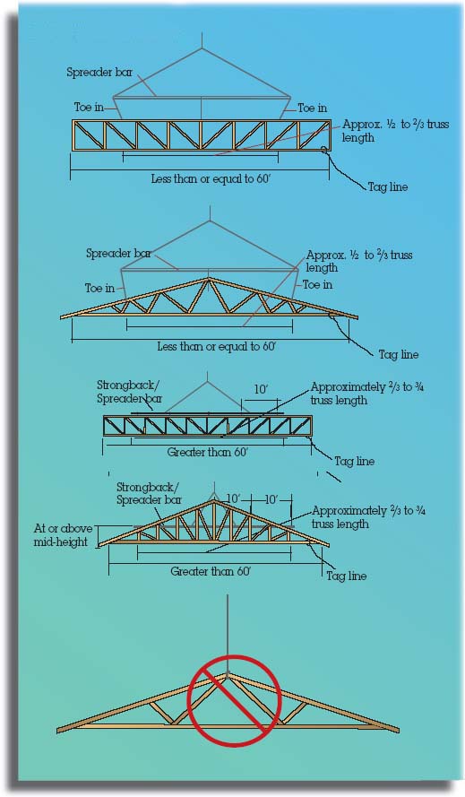
When flying trusses, you should attach the cables around the panel points. When the trusses are greater than 30’, a spreader bar should be used. The cables should toe inward to prevent the truss from buckling. If the truss is longer than 60’, you will need a strongback temporarily attached to the truss to stabilize it. (See “Flying Trusses” illustration, later in this chapter.)
If you have multiple trusses, you can build a sub-assembly of several trusses on the ground with cross braces and sheathing, then erect them together.
When trusses sit on the ground, on the building, or in place for any length of time, keep them as straight as possible. They are more difficult to set in place and to straighten if they have not been stored properly on site.
Structural Composite Lumber (SCL)
Structural composite lumber (SCL) is an engineered wood product that combines veneer sheets, strands, or small wood elements with exterior structural adhesives. The most common of these products are laminated veneer lumber (LVL), parallel strand lumber (PSL), and laminated strand lumber (LSL). Their names pretty well describe the differences between them.
Like other engineered products, structural composite lumber requires that you follow the engineered specifications that will appear on the plans. Sometimes the specifications simply indicate the use of a particular piece of SCL in a particular location. For larger jobs, you will find the SCL requirements called out in the shop drawings or the structural plans.
Because these are engineered products, you must consult the design engineer before you can drill or notch. Some manufacturers provide guidelines for drilling and notching, but this is not typical.
SCL has the advantages of dimensional consistency, stability, and availability of various sizes. It is important to note, however, that where dimensional lumber 4 × 10s, 4 × 12s, etc. can shrink significantly, SCLs have minimal shrinkage. The engineer should allow for this in the design so that you will not have to consider this factor when using SCLs as the plans specify.
Note that SCL studs are becoming common in building tall walls. They provide a degree of straightness that dimensional lumber does not. Although they are heavy and, as a result, not so easy to work with, they make nice, straight walls.
Conclusion
Engineered wood products come in a variety of forms. Becoming familiar with these products is important if you plan to work with them. Always be sure to follow manufacturers’ directions, and always consult an engineer if you plan to cut, notch, or drill engineered wood product components.
Forklift setting glu-lam beams

Pitched Truss Parts

Lateral Truss Bracing
Flying Trusses

Glu-lam Beam Weight Chart